")
It will only drop to the 9 volts (may be 8) when the points are closed.
Replaced the condenser and no change . I also set the gap on the points again,checked the plugs and the plug gaps before I took it out . Also checked all the connections and every thing looks good . I did notice the points have a hole in the center of the stationary side . Is this normal ? I looks like it was made that way . I didn't notice it last season when I put them on but I don't remember points being like that in the past .
Any way I'm thinking about putting a pertronix electronic ignition on it. At least that would eliminate 2 componets in the chain .Then I though I would change the plugs ,wires , distributor cap and rotor button again . I hate to do it since they are all new but something some where is breaking down and if I do all that I will basically have a new ignition system.
Also I should add . I just changed the outdrive before I put the boat in the water this year . I can't imagine how that could affect anything but I though I should throw that out there .
So what I'm saying is with the tach unhooked it runs crappy but better.
also I checked the voltage at the positive terminal on the coil . Switch on= 5vdc . running =12vdc . switch on with negative terminal open =12v . It only drops to 5V if I have the ground hooked up on the negative terminal.
At this point I have no clue . I can't figure out what the tach wire could have to do with anything .
sounds as if the resistor wire has an issue, you should see roughly 9 volts with the key on and sllightly higher with engine running - 12 volts running is too high and causing the points to overheat/burn prematurely
the tach gets it signal from the coil, a faulty tach can cause a no spark issue
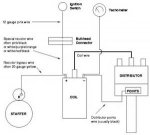
the negative side of the coil has the ground controlled through the points, i.e. points open path to ground is through the tower to dist cap, points closed path to ground is through points and back to battery through engine ground
WAIT!, You should only have ONE wire to the Dist, coming off the Coil Neg - (It acts as a ground), Plus the gray tach wire on coil Neg.
Then you should have 12volts going into the coil Plus + side, ONLY DURING cranking/starting, then becomes a Dead wire (the starter solenoids job) Next, under 9volts for RUNNING from the Resistor wire to the Plus + side. That's the voltage your coil should run at, and you should have a Non-Resistor coil Stock! (std. equip.)
no, it will always be around 9 volts - due to the resistor wire, the only time you will see more is during starting
Okay, here's your Fix:
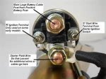
The starter solenoid small terminal on the right saying "S" is for start 12volts Pos + it should only be powered during start, to give you full 12V. for starting/cranking, then it goes dead during Run! and your Resistor wire 9volts (or whatever?) takes over to save your points, & Run your boat! That's it, you have to determine which is your resistor wire, & which is full power?
I'm sure one of the colored wires you have is the resistor, & one is full power. Check the wire at the solenoid that it's on the right terminal marked "S", if so it should be dead with your ignition switch on "Run", and a full 12V on Start/Crank. If not your solenoid is wired wrong, or bad!
I'm guessing your white wire is the resistor wire, and only powered in the Run mode of your ignition switch.
The diagrams I posted, are generic (so wire colors don't match yours) but, you should understand how it all works now.
By the way, the white wire probably comes FROM your shift switch, which is powered till you shift out of gear, then it's momentarily dead till you get thru your shift, okay?
ok thanks ,My purple yellow is wired to that terminal on the solenoid .I'll take some reading and make sure the solenoid is good .
I'll post back tomorrow with the results .
According to ohms law you get a voltage drop across a resister proportional to the currant flow. With the points open you get no flow, so no voltage drop.
You shouldn't have that much voltage when it's running. The only reason I can think of is if the points aren't staying closed long enough. How is the dwell?
If you can separate the wires? Take them off, then check voltage at the Solenoid wire in "ON" or "Run" position of the ign. switch, it should be O volts!
Then check at the Solenoid wire, with the ign. switch at the "Crank/Start" position it should be 12V or battery voltage.
If not, your Solenoid is bad. If all is well here, then there's a different problem.
The Resistor wire, (which probably is not even copper) but white metal should read under 12 volts with the ign. switch at ON/RUN. I'm not sure about crank, if it's powered then?
Also, remember there should only be one wire on the Neg - terminal going to the Distributor,,, plus the gray tach wire. You cannot add another ground wire here, or it will SHORT OUT the whole system! Theoretically you will have NO SPARK!
I don't have a dwell meter . I set the points with a feeler gauge
I separated the wires and the solenoid works as you described . I didn't check the other wire in the on position but I did check it with the engine running and I got 12v . ( I pulled the solenoid wire off while it was running and measured the voltage on the coil post while the resistor wire was still attached .)
I changed the resistor wire and I still have 11.5 to 12 v on the positive side of the coil . this is with the engine idling . It jumps to about 12.5 when reved . I tore open the wiring harness and spliced the new wire in where the old wire was spliced in . I took the readings while I still had the harness open and since I saw it was still high voltage I took a reading where the resistor wire splices in coming off the alternator . I had 12.57 coming straight off the alternator while idling . this seems normal to me . At first I thought that maybe the alternator was putting out to much voltage but that doesn't seem to be the case .
BTW the old resistor wire measures 2.5 ohms the new wire measures 1.5 ohms . I feel like I'm going backwards .
Also there are only 2 wires on the neg post . dist and tach.
i don't have an ammeter so I have no Idea what amperage the alternator is putting out . I guess I could open the ckt and get the current that way, then figure out what size resistor I need to drop the voltage to 9v .