1964 Johnson 3hp Model JH19A Serial # 101739 Rebuild

helicopterjohn

Seaman Apprentice
Joined
Jul 18, 2012
Messages
40
Hi racerone,

No doubt, 53 years is a long time I am sure many hands have touched this engine. Just thought I would take a little time and cash to hopefully bring back this worthy engine.

John
 

racerone

Supreme Mariner
Joined
Dec 28, 2013
Messages
38,411
Yes, they are nice motors.--Have a few myself and also boxes with many good parts.
 

helicopterjohn

Seaman Apprentice
Joined
Jul 18, 2012
Messages
40
Update:

Started the re-assembly process today. Cleaned all the parts, installed the pistons and rods, torqued the rod bolts, installled the lower half of the crankcase housing and torqued all the bolts to specifications, installed side cover and associated gasket, installed cylinder head with new gasket and had compression readings of 70 PSI on both cylinders, installed the magneto housing and lower housing.

Tomorrow I will try and find some 7mm solid core spark plug wires. I was unsuccessful at the local auto parts stores. I will check with local lawnmower shops and my local Johnson outboard dealer.

QUESTION: Is there any particular coil that has to be synced with a particular cylinder i.e. engine top/engine bottom The ignition wires were removed from the plugs when I acquired the motor? Note: One of the wires had a red metal clip on the exterior.

Once the new spark plug wires are installed I will install the magneto including all new points and condensers setting the appropriate point gaps. Then I will install the carburetor and do the link and sync setup. Then comes the gas tank with associated fuel line and fuel filter. Once all that is done I will install the recoil starter which should complete the upper unit.

1964 Johnson JH19A 3hp Short Block Re-Assembly


1964 Johnson JH19A 3hp Short Block Connecting Rods Installed With Anti-rotation Keepers On Rod Bolts


1964 Johnson JH19A 3hp Side Cover Plate And Associated Gasket Installed.


1964 Johnson JH19A 3hp Compression Check #1 Cylinder. 70 PSI


1964 Johnson JH19A 3hp Compression Check #2 Cylinder. 70 PSI


1964 Johnson JH19A 3hp Magneto Housing Installed.


1964 Johnson JH19A 3hp Front View Magneto Housing.


1964 Johnson JH19A 3hp Flywheel Test Fit.


1964 Johnson JH19A 3hp Front View Flywheel.


1964 Johnson JH19A 3hp Bottom Housing Installation.


1964 Johnson JH19A 3hp Magneto Plate.


helicopterjohn

Seaman Apprentice
Joined
Jul 18, 2012
Messages
40
Spark Plug Wiring:

I found this photo on the internet for a similar OMC 2 piston outboard. In the picture is showed the longer blue wire went to the bottom cylinder. Would my engine be wired the same way?

Thanks in advance for your valued input.

John

1964 Johnson JH19A 3hp High-Tension Leads Spark Plug Wires


racerone

Supreme Mariner
Joined
Dec 28, 2013
Messages
38,411
In picture # 2 the crankcase half was not yet properly cleaned / prepared for re-assembly work.--Sorry.
 

helicopterjohn

Seaman Apprentice
Joined
Jul 18, 2012
Messages
40
I did some more research after posting this morning and you are correct. I also noticed there was a metal tag on one of the wires. Taking a closer look it was engraved UP. It came from the front coil which also confirmed your statement. The marine dealer that sold me the wires also indicated that the tagged wire is usually the #1 (Top) cylinder.

I found some new solid core wires and OMC spark plug end rubber boots and associated metal clip ends. I installed them set the points and did the link and sync as discussed in this thread. I probably should still purchase a new set of spark plugs.

I am still working on the gas tank so I shot a little fuel in the carb, gave her a tug and she fired right off and ran for a few seconds. I also installed the foot and checked the oil. It was low so I added a little gear oil to the lower unit.

Hopefully, I will get the gas tank fixed within the next few days and see how she runs. I will keep you guys posted on the outcome.

Thanks again guys for all your valued input and suggestions. From the junk pile to running condition in a few weeks. Ha Ha

John
 

helicopterjohn

Seaman Apprentice
Joined
Jul 18, 2012
Messages
40
Update:

Question: Does anyone have a picture that shows a operational tilt mechanism for this particular motor. Mine seems to be missing some parts. If you look at the pictures below you will see some welded tabs on the horizontal rod that look like something was attached but broken off.

Any help would be appreciated.

Thanks, John

1964 Johnson JH19A 3hp Tilt Plate Mechanism.


1964 Johnson JH19A Tilt Plate Mechanism Missing Parts.


1964 Johnson JH19A 3hp Tilt Plate Mechanism Ratchet Pockets.


1964 Johnson JH19A 3hp Tilt Mechanism Plate Casting Number.

 
Last edited:

helicopterjohn

Seaman Apprentice
Joined
Jul 18, 2012
Messages
40
Update:

1964 Johnson JH19A 3hp Foot Installed.


1964 Johnson JH19A 3hp Link And Sync Picture. Throttle Lever At Correct Postion And Carb. Rod Just Touching Cam.


1964 Johnson JH19A 3hp Link And Sync Picture CloseUp View. Throttle Lever At Correct Postion And Carb. Rod Just Touching Cam.


1964 Johnson JH19A 3hp Prop Shaft View (Shear Pin Intact).


1964 Johnson JH19A 3hp Prop Installed.


1964 Johnson JH19A 3hp Front View Minus Gas Tank.


1964 Johnson JH19A 3hp CloseUp Side View Minus Gas Tank.


1964 Johnson JH19A 3hp CloseUp Side View Minus Gas Tank.


1964 Johnson JH19A 3hp Side View.


1964 Johnson JH19A 3hp Rear View Minus Gas Tank.


helicopterjohn

Seaman Apprentice
Joined
Jul 18, 2012
Messages
40
Additional Information for Post #31.

I found this on E-Bay but was for a JW-22 motor not the JH19A that I have. They may both use the same Tilt Lever. Can anyone confirm this???

John

Johnson 1967 JW-22 Motor Part (3HP) ? Tilt Lever


helicopterjohn

Seaman Apprentice
Joined
Jul 18, 2012
Messages
40
Update: Tilting lever, associated locking assembly and elliptical cam ring that is molded into the lower foot

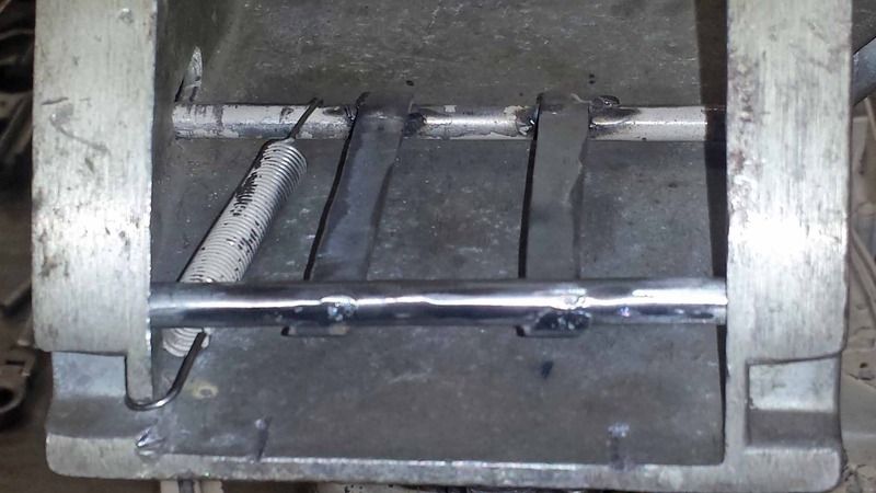
After looking at the picture I supplied in Post # 51 I decided to repair my broken tilting lever by adding a lower support rod and associated support tabs. Please excuse the poor welding job as it is not one of my better skills. Not too pretty but it works. I may get my buddy to powder coat it for me. Ha Ha

When the motor is set for forward operation The cam ring position is on the low side of the cam ring which disengages the locking assembly. No locking of the assembly is required in this position as the torque of the motor applies pressure to the transom of the boat and keeps the motor down.

When the motor is set for reverse operation (turned 180 degrees) the cam ring position is on the high side of the cam ring which engages the locking assembly. This is required as the torque of the motor wants to kick up the motor and the locking assembly keeps the motor from kicking up.

Note: The tilting lever can only adjust the fixed angle of the motor while in the forward operation position by pulling up on the lever handle and moving the tilting lever to the appropriate detent position.

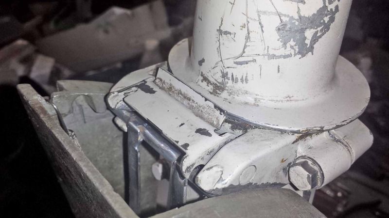
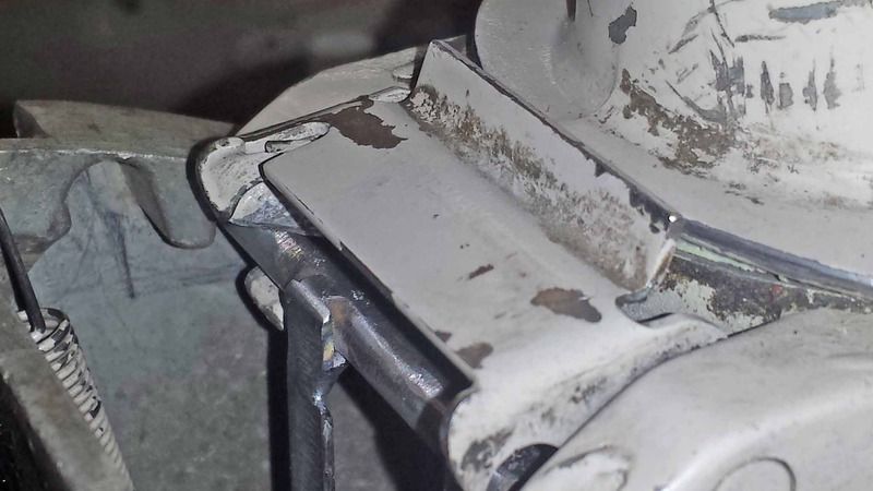
1964 Johnson JH19A 3hp Tilting Lever Lock Assembly (Open Position On Low Side Of Cam Ring)


1964 Johnson JH19A 3hp Tilting Lever Lock Assembly (Closed Position On Low Side Of Cam Ring) Note: That When I Depressed The Lock Assembly The Bottom Edge Is Now Away From The Cam. When Motor Is Turned 180 Degrees The Cam Will Lock The Lever.


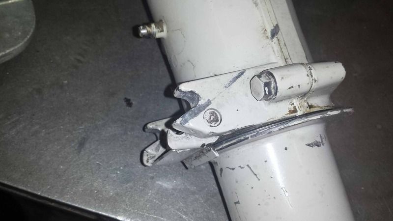
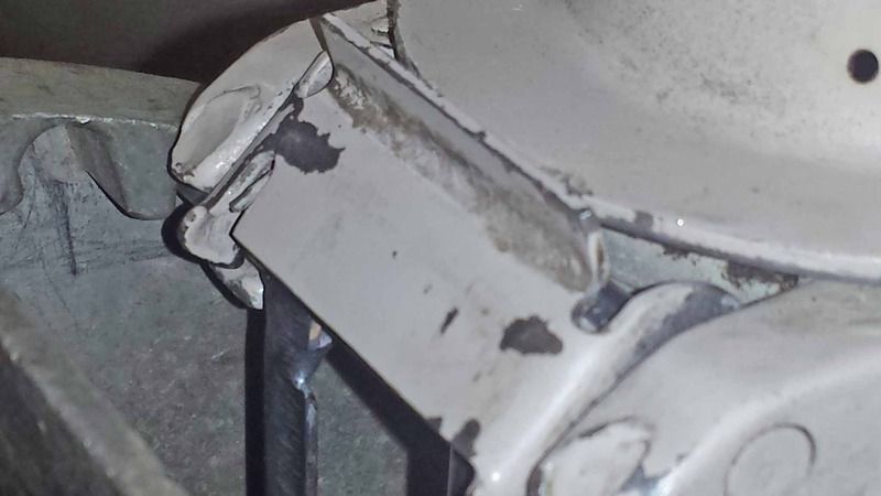
1964 Johnson JH19A 3hp Low Side Of Cam Ring Allows Free Tilting Of The Motor In Forward Position.


1964 Johnson JH19A 3hp Tilting Lever In Forward Position (Lever Lock Is Disengaged) The Torque Of The Motor Keeps The Motor Against The Transom.


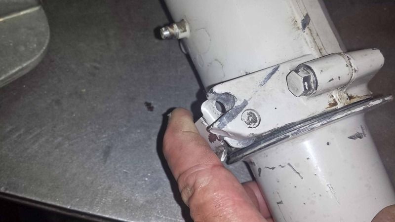
1964 Johnson JH19A 3hp High Side Of Cam Ring Engages Lock Assembly When Motor Is Turned 180 Degrees For Reverse Operation. This Prevents Motor Kick Up During Reverse Operation.


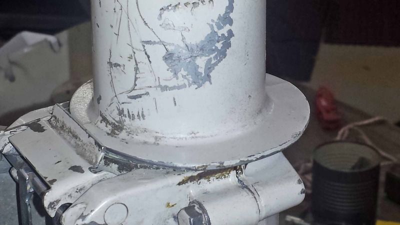
1964 Johnson JH19A 3hp Tilting Lever Repair. Please Excuse The Poor Welding As That Is Not My Strong Suit. I added The Lower 1/4" Diameter Rod And Associated Support Tabs. Not Pretty, But It Works. I May Get My Buddy To Powder Coat It For Me.


1964 Johnson JH19A 3hp Tilting Lever Lock In Position For Forward Operation On Low Side Of The Cam Ring.


helicopterjohn

Seaman Apprentice
Joined
Jul 18, 2012
Messages
40
Hi,

Couple of questions?

1: What would be the normal temperature operating range for this motor? I have a infra red temp gun.

2: Are the water pee holes for this motor the 4 small holes about 1/8" diameter just below the reverse cam locking ring on the rear side of the lower unit tube housing?

Thanks in advance for any information you can provide.

John
 

helicopterjohn

Seaman Apprentice
Joined
Jul 18, 2012
Messages
40
Update:

Good News! I finally got the motor started and running in a test barrel and it seems to be doing just fine. It was nice to finally hear it run after all of this work. Little spurts of water were coming out of the 4 holes mentioned in question #2 of post 53 while running. My assumption would be if water is coming out those holes the water pump is working properly. I will do some temperature readings tomorrow. One bit of information was that the temperature should be around 150 degrees. Not sure if that is correct. I will know more tomorrow when I check with my infra red temperature gun.

Got my repaired gas tank back, received the new gas tank filter, installed new copper tubing from gas tank to carb. with no leaks. Purchased a used steering arm and cleaned it up and had a friend of mine powder coat it along with my tilt lever, choke knob and low speed mixture knob.

1964 Johnson JH19A 3hp New Fuel Tank Filter.


1964 Johnson JH19A 3hp Powder Coated Steering Arm.


1964 Johnson JH19A 3hp Powder Coated Low Speed Mixture Knob And Choke Lever


1964 Johnson JH19A 3hp Powder Coated Tilt Lever


oldboat1

Fleet Admiral
Joined
Apr 3, 2002
Messages
9,612
normal temp is 120 to 140 -- depends a lot on water temp in the lake or barrel. Shouldn't be over 160 degrees F. It's sufficient/normal to get light to medium spray from the holes.
 

helicopterjohn

Seaman Apprentice
Joined
Jul 18, 2012
Messages
40
Hi oldboat1,

Thanks again for contributing valuable information along the way of this rebuild.

John
 

jqning

Recruit
Joined
Jul 7, 2018
Messages
4
Hi John, you’ve got the most complete reference on the tilting mechanism so I’m hoping you can help.

My lever is a lot like yours. I’ve got the horizontal top bar but the two vertical pieces and the bottom bottom horizontal bar are gone. I’ve ordered a replacement.

Can you explain how that bottom spring clip works? I feel like mine is backwards but it look is totally original. So I guess I’m saying I can’t figure it out and if I need to make a change I’d like to get thatvworking before the tilt lever gets here. And I hope you can help.

I made a video of my clip.

https://m.youtube.com/watch?v=rV1cNVn_5bU
 
Top