1969 Sea Ray SRX Pachanga Build Thread

Natesms

Chief Petty Officer
Joined
Sep 8, 2012
Messages
464
Re: 1969 Sea Ray SRX Pachanga Build Thread

Amazing amount of progress in such a short period of time. Keep up the good work!
 

Propellerhead

Petty Officer 3rd Class
Joined
Nov 15, 2013
Messages
94
Re: 1969 Sea Ray SRX Pachanga Build Thread

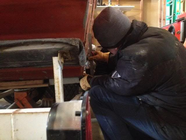
Well, this will be a short update. I was able to get a little work done this weekend, but it's frigidly cold and I'm feeling under the weather, so this is what I could accomplish. I had some help today, so while my buddy was doing other things, I decided to measure the boat for the x-dimension. Basically, with the new transom in place, I need to measure everything out so I can cut the hole correctly for the outdrive to pass through. The first thing you have to do is find the exact center of the boat, then you have to figure out the x-dimension, which is the vertical position of the engine crankshaft centerline. Everything is positioned based off of this measurement.


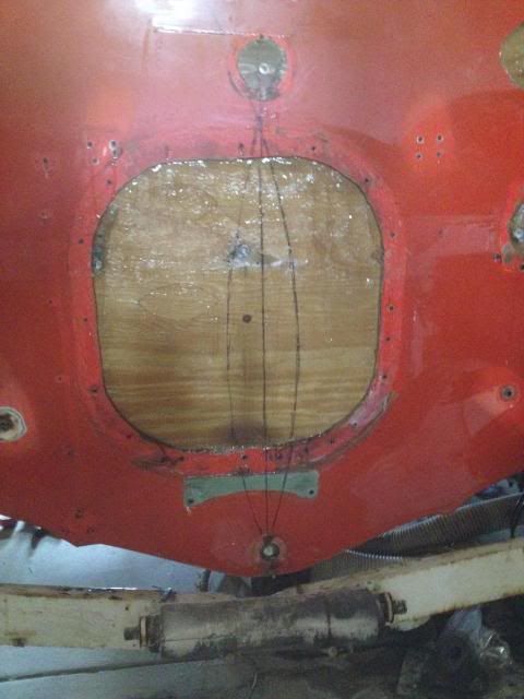
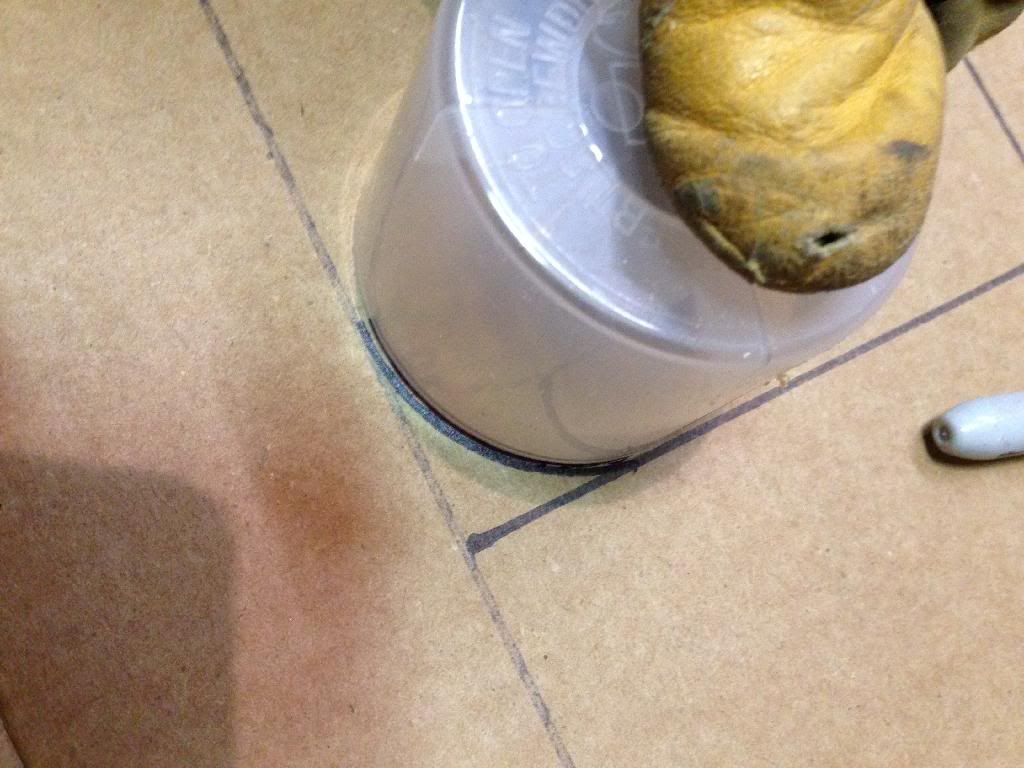
We found the boat centerline by tying a sharpie to a piece of string that's a consistent length. It doesn't really matter what length it is, as long as it's slightly more that half the width of the boat. We then drew an arc on the transom by holding the string on a specific point on the side of the hull (we used one of the outboard chines). Once this is accomplished on both sides, as you can see in the picture, where the arcs intersect on the top and bottom of the transom are two points that are in the exact center of the hull. After that, it's as simple as taking a straight edge and connecting the two points with a line. This is the centerline.

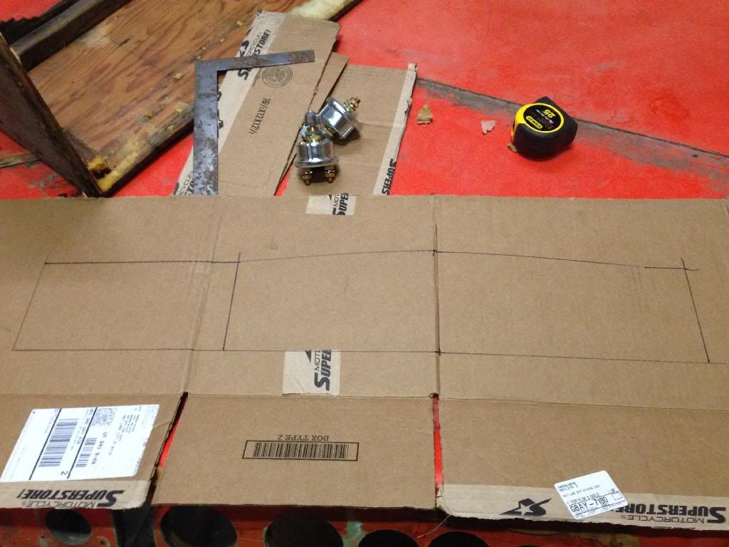
Now it's time to find the x-dimension. You can look this up in the Mercruiser manuals, but basically what it says is that the stock x-dimension is located at 13 9/16 inches from the bottom of the hull. However, you can modify this number based on what the intended purpose is for your boat.


I set my square to 13 9/16 inches.


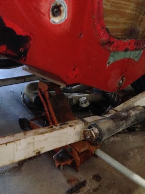
I had to jack the boat up off the trailer to get my square under the hull.


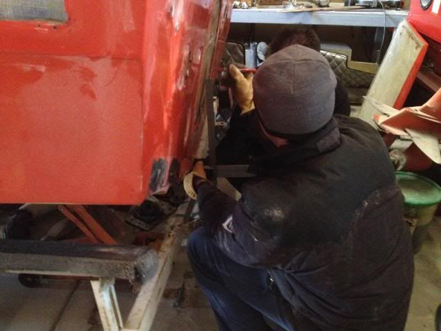
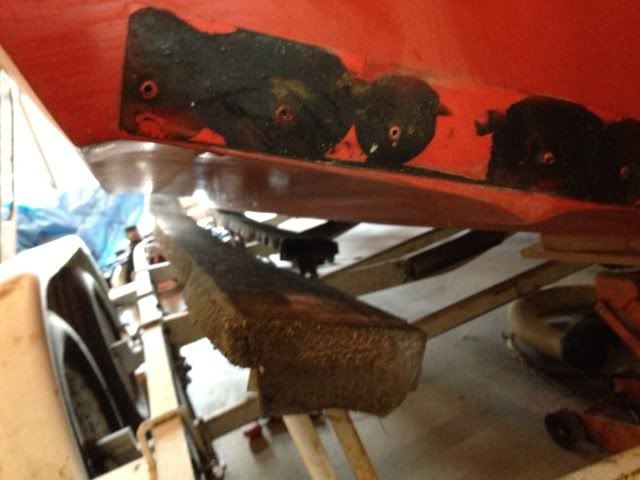
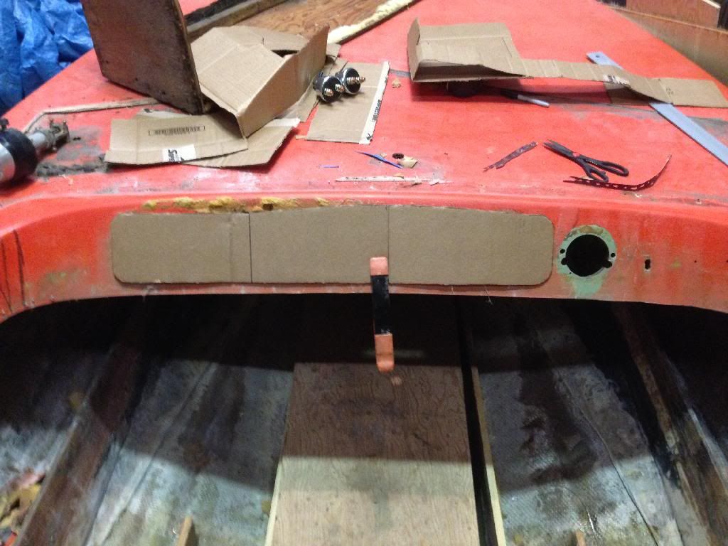
We put a straight edge under the hull and used the square to measure up 13 9/16 inches. You have to use a straight edge off of the hull because the transom is at an angle. Since it isn't 90 degrees you can just measure up from the bottom. But anyhow, it worked and I marked the x-dimension on the transom.
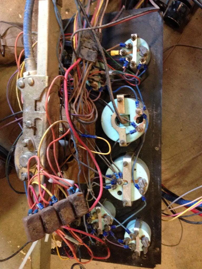
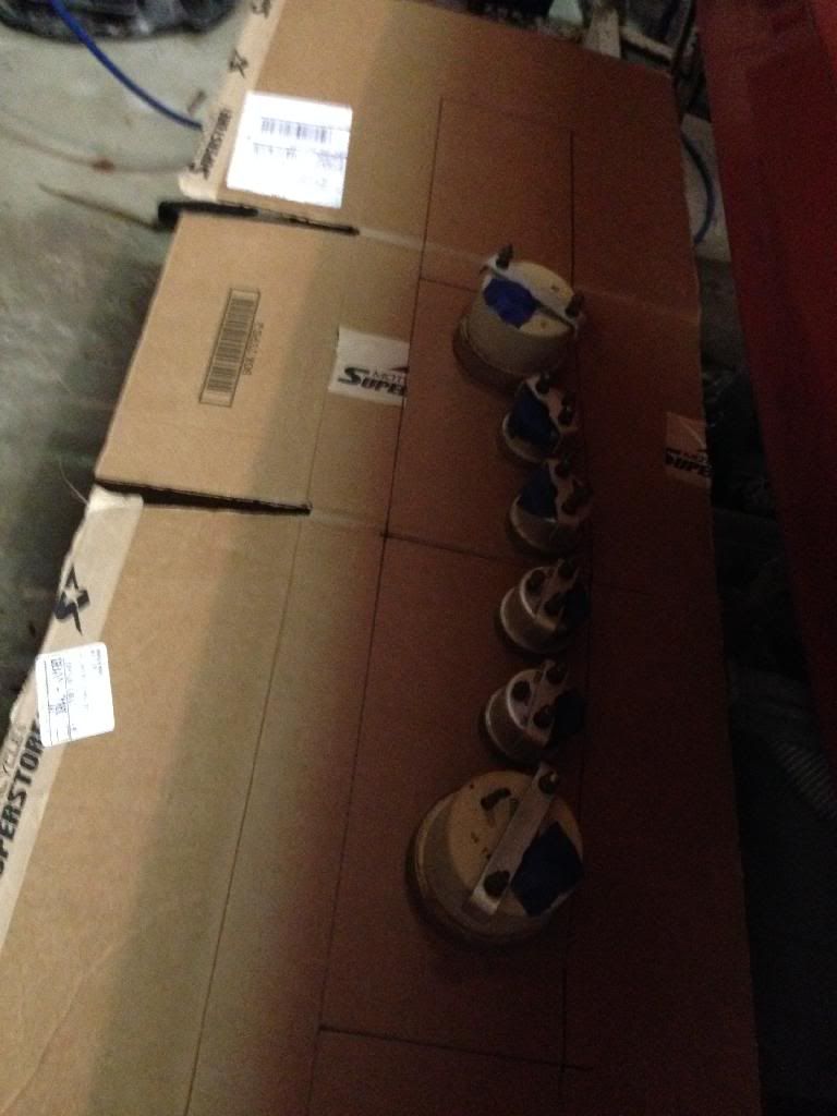
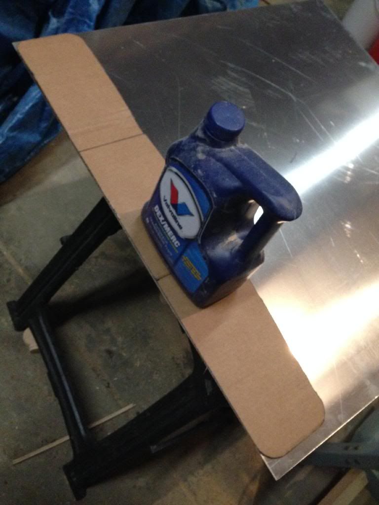
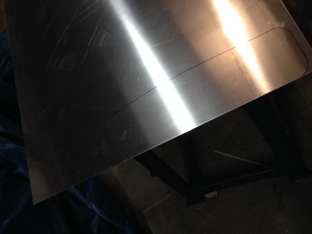
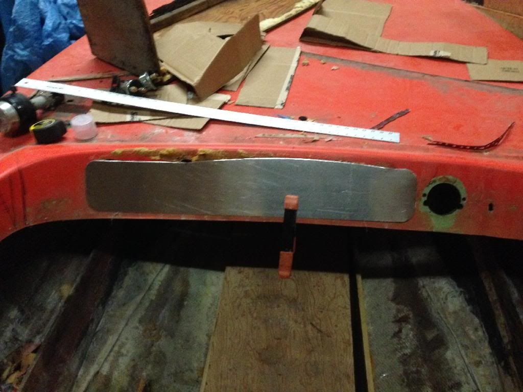
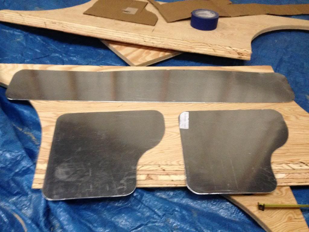
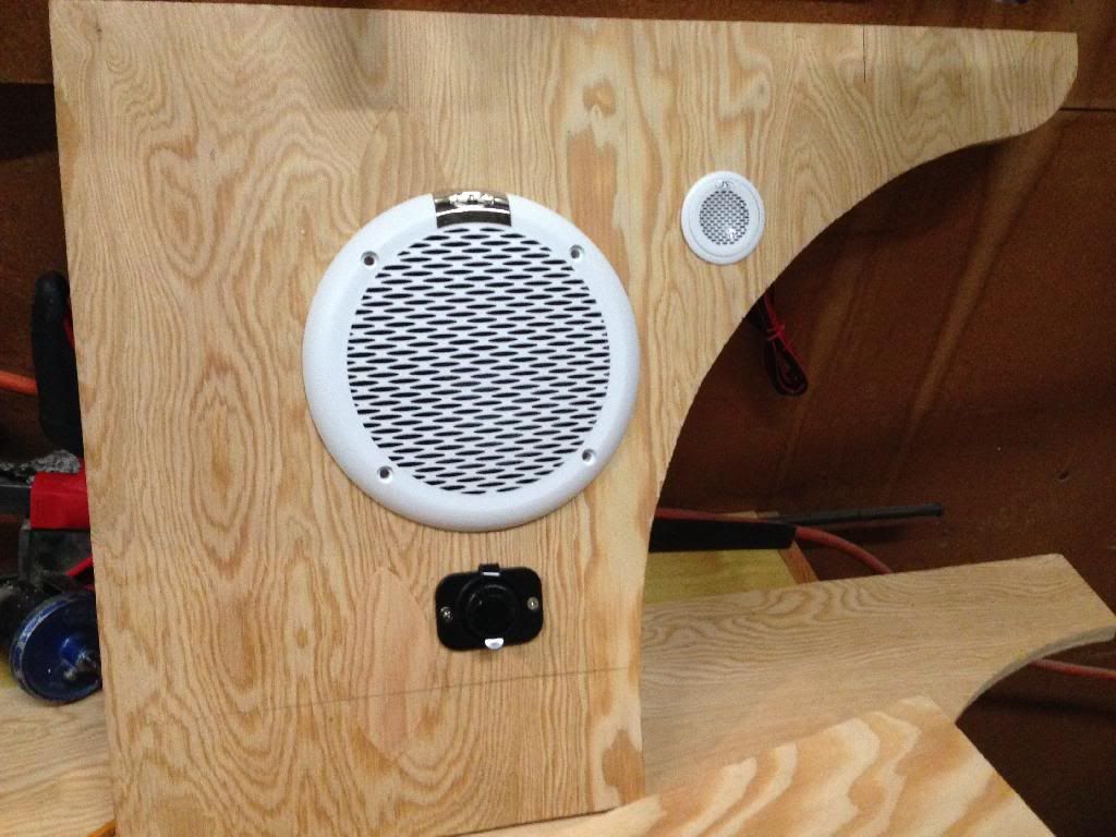
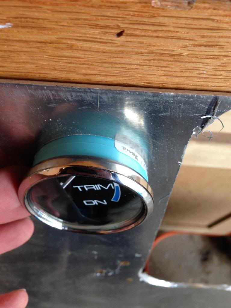
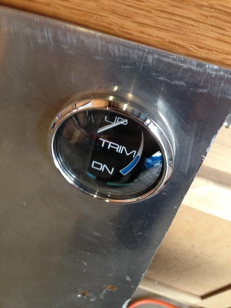
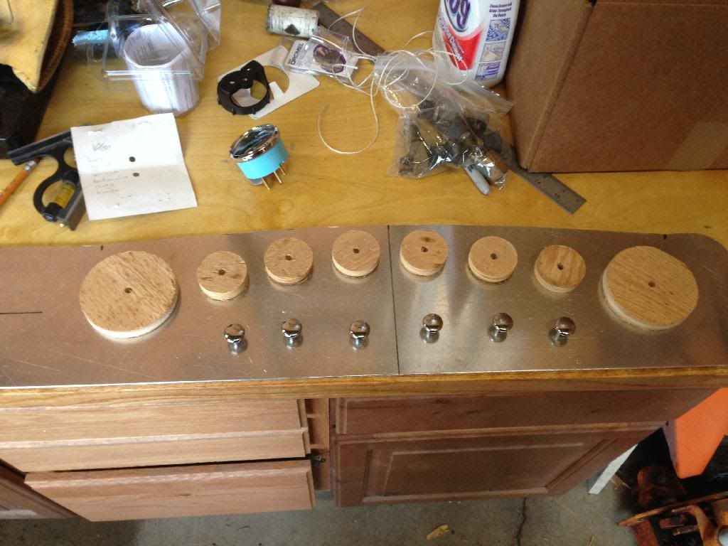
 

Propellerhead

Petty Officer 3rd Class
Joined
Nov 15, 2013
Messages
94
Re: 1969 Sea Ray SRX Pachanga Build Thread


I wrote "min" next to the mark, because it's possible to actually increase the x-dimension. Doing so will lift the outdrive out of the water a small distance, and reduce the drag from the water. It's a trick to get a little more speed out of the boat. I have a feeling that there isn't much room under my engine cover, I'm going to measure that next. But the way I see it, the stock x-dimension is the lowest the outdrive is going to be, hence "min."

So now I wanted to see what the maximum x-dimension was that I could get away with. According to Mercruiser, they don't recommend raising it more than 2.5 inches, but I've heard from some aquatic speed freaks that you can get away with up to 4 inches before you have to worry about buying special (read expensive) props. I measured the motor from the crankshaft centerline (x-dimension) to the top of the spark arrestor and it came to 21 1/4 inches. This is effectively the minimum distance I need between the x-dimension and the bottom of the engine cover.


In the meantime, I had my buddy Shea dig out the gimbal/transom assembly from the parts boat.


He took off the y-pipe, and started working on the gimbal housing itself.
 

Propellerhead

Petty Officer 3rd Class
Joined
Nov 15, 2013
Messages
94
Re: 1969 Sea Ray SRX Pachanga Build Thread


Much of the through-hull hardware was corroded beyond repair.


He got the gimbal housing separated and the parts boat transom removed. (I'll use this piece later for a keyhole pattern.) For now, I'm going to use the gimbal for a few measurements.


Since I'm measuring down the transom now, to see where my maximum x-dimension is, I need to find the angle between the crankshaft centerline and the transom. I insterted a mercruiser engine alignment tool into the gimbal bearing and put an angle gauge on it. Then, I put the same angle gauge on the gimbal mounting flange and subtracted the two numbers. The result was 101?.


I then set a protractor to 101?.
 
Last edited:

Propellerhead

Petty Officer 3rd Class
Joined
Nov 15, 2013
Messages
94
Re: 1969 Sea Ray SRX Pachanga Build Thread


Then I set a straight edge across the engine compartment opening and measured down 20 1/4 inches. (The actual engine height is 21 1/4 as I mentioned before, but there's an additional inch of clearance under the engine cover over the lip of the opening.) I used the protractor set to 101? and a straight edge to measure across to the transom to make my mark.


I wrote "max" next to the mark, since this is the highest possible x-dimension without hitting the engine cover. Disappointingly, the difference between "min" and "max" is only about an inch and a half. That's not a lot of "go-fast" room. I haven't completely decided yet, but I'm thinking that I'll probably leave the x-dimension in the stock, or "min" location so that I have some room on the top of the engine for an intake spacer, or difference spark arrestor. I can see if I can get a shortened outdrive later when budget permits.


Meanwhile, while Shea and I were working on all this, Forrest was completing the rear bench seat. Fit-test approved!

Well, that wraps up the progress from yesterday. I'll try to get out there again when I start to feel better.
 

Searayb

Seaman Apprentice
Joined
Jul 6, 2011
Messages
46
Re: 1969 Sea Ray SRX Pachanga Build Thread

You guys are going to town, nice work, thanks for the pictures.
 

Propellerhead

Petty Officer 3rd Class
Joined
Nov 15, 2013
Messages
94
Re: 1969 Sea Ray SRX Pachanga Build Thread

I have been! At least on my days off. I made some more progress today. I thought I'd get some more work done on the interior, specifically the gauge panel.

A1003E2E-2105-4EF4-B593-0A555BA9E1EE.jpg


This is the wiring behind the panel from the parts boat. Not only is it a rats nest, but this boat only had cheesy in-line fuses as well. That, plus some rusted out relays. I'm think I'm going to be wiring this boat from scratch. Oh well. After looking at that mess I didn't feel like dealing with it right then, but I figured I could make the new gauge panel. I didn't really like how the wood panel was laid out on the boat before, so I decided to make one out of aluminum.

F7CA6A4F-925D-472A-99FA-8DD43A1EE9C2.jpg


I took some measurements and drew out the shape that I wanted on some cardboard for a template.

8D3DDC24-82BB-492A-B47A-8DCF162E98B9.jpg


I laid out the gauges to make sure they all fit. These are actually the old gauges. I don't have the new ones yet, but they're going to be the same size. There are going to be a couple more since I'm adding a trim gauge for the Mercruiser outdrive and a depth gauge, but this is enough to give me an idea.

ADFDE8D5-8EE6-4C1A-BA2C-FA81071B4199.jpg


I did want rounded corners and a spray can cap gave me the curve that I wanted.

38C85460-7056-43D5-BEC4-4EC0BCD0F3F9.jpg


So, I cut it out and I like what I see.
 

Propellerhead

Petty Officer 3rd Class
Joined
Nov 15, 2013
Messages
94
Re: 1969 Sea Ray SRX Pachanga Build Thread

05D9CA7E-543A-430B-8A8B-C326C95C6A54.jpg


I laid the template onto some 13-gauge aluminum sheet for tracing. The tranny fluid is to keep it from moving around. I went with fairly thick aluminum because I want it to be able to handle the forces of push-pull switches without deflecting. Plus, the dash on the boat looks like Swiss cheese, it could use all the support it can get.

774D9371-F4B3-46CA-8747-66A0FEE8BE0A.jpg


Here's the pattern all traced out.

CB9BF84C-A78C-41DA-921E-C81B201E9176.jpg


13ga was a little thick for the tin snips, so I ended up using a cutoff wheel to cut it out. I cleaned up the edges with a coarse then a fine file, and this is what I ended up with.

D1A4FCAE-AAE2-4E07-B352-C9C1401CE110.jpg


I decided to make some similar panels for the sides of the cockpit. There's going to be switches, the stereo, the throttle, the Bennett trim tab gauges, etc. in these panels, so this is a way to dress them up a little. I used the same cardboard template method to do these.

8CDA51B1-A782-40BE-BE43-C404AA7D25AE.jpg


Since I had moved on to the side panels, I cut the speaker holes in the other rear panel (if you recall, I did the first one a couple weeks ago.) This one is the port side rear panel. I traced a line where the bottom trim overlaps and measured halfway in between the trim and the speaker so I could mount one of two 12v power outlets. (I'm doing one on the port side rear, and one on the starboard side forward.)

0F1C6ECA-F370-42EF-A338-61111B6DC8C9.jpg


This is how the panel turned out.
 

Propellerhead

Petty Officer 3rd Class
Joined
Nov 15, 2013
Messages
94
Re: 1969 Sea Ray SRX Pachanga Build Thread

EF53688F-77EB-4944-8535-56AE355D3057.jpg


I also noticed that the side panels I'm making don't quite fit flush to the bottom, so I set up a sacrificial fence on the table saw to cut a bevel in the bottom of the panels.

97B06AB8-E2ED-4C9E-8B32-C70A1BEE385F.jpg


This wasn't the easiest of cuts to make, but this is how the bevel turned out. This panel is ready for sanding, waterproofing and upholstery. I beveled the rest of the side panels but forgot to get a picture.

Well, that's it for now. Slowly but surely. I'll be back next week to work on it.
 

maryhannaj

Chief Petty Officer
Joined
Sep 22, 2013
Messages
422
Re: 1969 Sea Ray SRX Pachanga Build Thread

Hey Propellerhead. Great boat. Your doing a great job too. I'm so happy that I happened accross you thread. Thanks for taking such great pictures of your stringer install. Just so happens I just got finished up with grinder hell yesterday late. But I've been grinding on that stupid thing for weeks now. No kiddin either. It was a mess.
Anyhow, your documentation on your stringer install really helped me in how I could go about cutting and fitting my stringers and propping them up for measurment etc...
Once again, great boat and great thread too!
Oh yeah. I'm not too far away from ya man. If your still lookin for some 1708, I just worked out a hook up for some of us locals so we can get it in smaller then whole roll amounts with the help of a great local supply source. Shoot me a PM if you need some and want a location. It will still be a few days before it's available, but hopefully it will help us out.

Later man.
 

Propellerhead

Petty Officer 3rd Class
Joined
Nov 15, 2013
Messages
94
Re: 1969 Sea Ray SRX Pachanga Build Thread

Thanks, maryhannaj! I'm glad it helped. The grinding is the worst part, and I have more to do when the weather warms up. I think I'm ok on the 1708 because I ended up buying a whole roll, but I will definitely let you know. It seems like I always use more than I plan for. Do you have a thread for your build? I'll look for ya out on the lake!
 

maryhannaj

Chief Petty Officer
Joined
Sep 22, 2013
Messages
422
Re: 1969 Sea Ray SRX Pachanga Build Thread

No problem man. I'm glad you have it all covered. I'm restoring a 1982 Gaston bass boat. Did you decide to stop glassing because of temps? I'm just curious because that looks like a pretty dang nice shop your working in. Where's the heat?
 

Propellerhead

Petty Officer 3rd Class
Joined
Nov 15, 2013
Messages
94
Re: 1969 Sea Ray SRX Pachanga Build Thread

Yeah, I stopped glassing because it got too cold. It's actually an aircraft hangar. There's tons of space, but no heat, haha.
 

maryhannaj

Chief Petty Officer
Joined
Sep 22, 2013
Messages
422
Re: 1969 Sea Ray SRX Pachanga Build Thread

I got ya. A lot of juice of any kind to heat up a space like that. It almost looks like a place I know at Skypark airport in NSL. It looks like you'll have plenty do to keep you busy through the cold time though. Hopefully we'll start warming up in a few months anyway.
I'm just going to do my glassing in my garage with some small heaters and halogen lamps. I hope it will work out because I'm just about to where I need to start glassing.
Nice score on the motor by the way. It's nice to hear about good things happening to people. I watch those classifieds pretty closely and I think I remember that one being on there.
You could also just pick up that $4800 454 that's on there. She'd really move then!:lol:
I think she'd always be a bit thirsty though. Keep us posted man.
 

Propellerhead

Petty Officer 3rd Class
Joined
Nov 15, 2013
Messages
94
Re: 1969 Sea Ray SRX Pachanga Build Thread

Thank you! Well I've been at the shop for the the last few days, although, the first day I didn't have a chance to get anything done on the boat. Let's call it some much need "tow vehicle" work. :) Yesterday, I made some good progress on the instrument panel and side panels. So I had left off with the completed aluminum blanks, now I need to flesh them out with some equipment.


First things first, I needed to figure out exactly where the panel was going to be, and mark everything so I had a way of lining it up the same every time. I started by using a square to create index lines in significant places.


Then I lined up the panel and transferred the index lines to it.

I finally bit the bullet and bought a set of new Faria gauges. I figured I was going to eventually anyway, so I might as well do it now so I don't have to repeat any of this work. Well, the set was backordered, but I did get a couple of the new gauges, and the instructions for the smaller ones say to cut a 2 1/16" hole. Well, I went to the Home Depot and they didn't carry hole saws in that size, so I bought a 2". I figured better to be too small than too big. Now for the two big gauges, (the speedometer and tach) the Home Depot didn't carry a 3 3/8" hole saw either, but the overlap on those gauges is big enough that I can get away with cutting a 3 1/2" hole and it's not going to be a problem. (Don't worry, I'll show you guys a picture of the fancy new gauges set as soon as I get them.) :)


I wanted to see how close I was going to be with the small gauges, so I cut a test hole in some spare aluminum.
 

Propellerhead

Petty Officer 3rd Class
Joined
Nov 15, 2013
Messages
94
Re: 1969 Sea Ray SRX Pachanga Build Thread

74278A0A-596E-4173-9147-4EE187EEB771.jpg


As you can see, the gauge doesn't fit all the way in.

48E93DA4-9232-4875-A96A-859D86178307.jpg


Since it was so close, I didn't need a tool the was too aggressive. I ended up going with a dremel with an 80 grit flap wheel.

82BB8827-60BD-4271-B97E-6AACA5D29CAA.jpg


It did the job great. Three times around each hole was all it took.

0EC028C3-5DFA-419A-8E08-A48AB25881CD.jpg


So now to actually start laying out the panel. I started by using the same hole saws for the gauges to cut out plywood circles. They're obviously going to be a little smaller than the actual gauge, but you can get a good idea. Plus, the circles will come in handy later.

21BC1B34-4B49-41B1-BEE7-2944ADED7EE1.jpg


Two big gauges and six little ones.

CE48244A-A47C-4DCE-80EA-D8988D0EA1D8.jpg


I spent some time looking at classic boat instrument lay outs to see what people where doing. I played with the plywood circles a little bit, but this is what I settled on. I also laid out the new chrome knobs I got for the push-pull switches.
 
Top