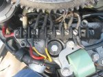
I have noticed some discrepancies between my wiring diagram and what is really happening at my Wire Terminal. On the attached photo, each wire is colored and leading to, as described below. I am calling the Main wiring harnes from the controller, the "Main Buss":
From Left to Right
Terminal 8
Top - Red to Main Buss
Bottom - Red to Rectifier (VARO R315 7744)
Terminal 7
Top - Brown to Buss (Should be Grey to tach)
Bottom - Yellow/Grey to Rectifier
Terminal 6 (Shunted to 7)
Top - Yellow/Grey to Stator
Terminal 5
Top - Yellow to Stator
Bottom Yellow to Rectifier
Terminal 4
Top - Purple/Yellow to Temp Sender on Water Passage Cover
Terminal 3
Top - Purple to Temp Sender
Top - Brown to Main Buss
Terminal 2
Top - Brown/White to Main Buss
Bottom - Purple/White to Choke
Bottom - Purple/Yellow to Choke
Most of these are correct with respect to my wiring diagram. On terminal 7 the wire could be grey and now just looks brown or there has been a little work done here. I hooked my tach up to the grey wire at the controller and it works fine. On terminals 2 and 3 the purple and purple/white wires from the main buss appear to have been changed to brown and brown/white
What is really odd is how the temperature sender and the choke are wired. This can't be right. Both choke leads go to the same terminal (2) instead of being across terminals 2 and 4. The temp sender should be across terminals 2 and 4 as well, but is connected to terminals 3 and 4 instead.
Is temp sender at the water passage cover a part of the 'Fast Start' system that I did not think I had. Is this correct? If so, it appears that it is disconnected, bypassed, or otherwise tampered with. Hopefully the reason I am having problems with setting my timing correctly. But i am affraid to just go and re-wire everything as it should be without checking with you all first.
Please let me know if I need to clarify anything.