1981 Sportcraft 270 repair underway - transom, stringers, & repower

Status
Not open for further replies.

WalleyeSniper

Petty Officer 2nd Class
Joined
May 15, 2018
Messages
108
Came across an 81' Sportcraft 270 for $1500 and jumped on it. The hull is in great shape, so that's essentially what we were buying. Here on Lake Erie's central basin, we love these boats and I've have owned a few Sporties thus far.

We decided to do the stringers, transom, and repower her. Just started in on her and figured we'd share the progress and welcome and insight, tips, advice, or opinions anyone may have along the way on this. I have many questions as well, so figured this would be a good way to condense them into one thread instead of muddying up the forums with tons of posts. Here we go!
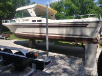
20210605_160648_HDR.jpg
Starting Vessel (She's now on the trailer with cribbing built in 4 locations down her length for support during the build).

1981 Sportcraft 270
Engine/Power: Merc 225 (GM 305/5.0)
Drive/Trans: Velvet Drive 72C (10-18-006)
LOA: 27'
Beam: 10'
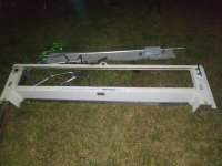
20210617_223136.jpg
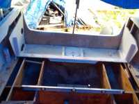
Cut the rear cap section off to expose the fuel tank and transom. I know I should remove the entire cap, pull out the tub insert, and etc. But, we don't have the resources nor desire to pull the cap. So, figured just cutting the rear section off is best and we'll reattach & strengthen it at the end.
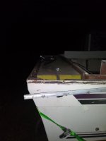
20210617_223159.jpg
Fuel tank exposed and ready to come out.
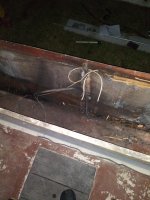
20210618_012532.jpg
Fuel tank removed. This transom has seen better days for sure... There's only a single sheet of 3/4in plywood in there. Even though it's just an inboard and no real driving force is exerted on the transom, I feel like it's going to need to be at least double that thickness for a kicker motor install, no?

Next we'll be cutting the floor out, and then it's nothing but demo of all the old nasty wood and glass to get this to a near bare hull ready for new stringers, transom, and sole.

How thick do we need to go on this transom to add a 9.9hp kicker motor? It's currently only 3/4" thick ply in there. Should I double it and go 1.5" thick overall?

Thanks for looking! Any advice or guidance is welcomed and very much appreciated.
 
Last edited:

WalleyeSniper

Petty Officer 2nd Class
Joined
May 15, 2018
Messages
108
Nice boat! Looking forward to your rebuild.
Thanks man! I'm excited to be finally doing a complete makeover on one of these. I'm hoping to get lots of good layout ideas from the community as to what to do for the interior and etc. Make this thing the ultimate fishing machine hopefully.

Tomorrow, we're planning on removing the engine and Velvet Drive/prop/shaft etc. Hopefully anyways, if all goes to plan.

I'm definitely going to post pictures along the way. If not for anything other than record of the build.
 

WalleyeSniper

Petty Officer 2nd Class
Joined
May 15, 2018
Messages
108
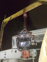
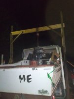
Pulled the old tired Merc 255/GM 350 that was in the boat. We built a wooden gantry with two 2x10's as the crossbeam up top to take the load, and used a 2 ton manual chain hoist to do the heavy lifting.

We put the boat back on the trailer to do this part. Pulled the engine up, then pulled the boat/trailer forward, and then lowered the engine to the ground. It went rather smoothly and wasn't as sketchy as I anticipated it you be. You know, using a creaky wooden DIY gantry and all.

20210625_222111.jpg
Pulled up high enough to clear the transom, and just pulled the whole trailer out from underneath it.

20210625_222059.jpg
A little bit better picture of the gantry we mocked up. It was EXTREMELY stout, and didn't so much as make a peep or stress out one bit. We drilled holes and used carriage bolts to tie everything together instead of just screws or lags.

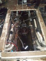
More pics to follow of this crappy engine bay. For some reason, the engine mounts weren't bedded directly into the stringers, but screwed into two 3/4" pieces of plywood used as spacer blocks ON TOP of the engine beds. So, I'm gonna have to figure out to just make the engine beds taller when redoing them, OR, find taller engine mounts. I definitely don't want to put two pieces of 3/4" plywood spacers back in there, lol (Pics coming of this debacle).
 

kcassells

Fleet Admiral
Joined
Oct 16, 2012
Messages
8,738
Pretty amazing what a little spit and dirt can do. On your way now. You'll be finding all kinds of "Noway" they built it this way.
 

WalleyeSniper

Petty Officer 2nd Class
Joined
May 15, 2018
Messages
108
Pretty amazing what a little spit and dirt can do. On your way now. You'll be finding all kinds of "Noway" they built it this way.
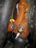
Yeah, I've been running into "noway's" left and freaking right :LOL:. Here's a good example of it:

20210622_195159.jpg
Automotive water pump with secondary water temp sender WIRE NUTTED in there. :rolleyes:

20210626_010729.jpg
If you look closely, the engine beds have those two layers of little plywood chunks on top too. I mean, the engine is at the right height that way and centered with the trans and prop shaft. I'm just not sure if the MFG did that or the previous owners. And if previous owners, then where the hell did the original engine mounts go that reach low enough to not have to have two 3/4" plywood spacers? Lol

20210626_010806.jpg
Here's one spacer section glued to the engine bed. The other was in the pool of water I have yet to drain because I can't get a high enough angle on the trailer. The cribs and stands will angle enough to drain it though.
 

kcassells

Fleet Admiral
Joined
Oct 16, 2012
Messages
8,738
Whats that smell?? Oh yea...total rehab. Yum yums! Grab a little cheap drill pump.
You keep going and you won't be surprised how many boats cam off the line from factory like
El Crapo.
 

WalleyeSniper

Petty Officer 2nd Class
Joined
May 15, 2018
Messages
108
Whats that smell?? Oh yea...total rehab. Yum yums! Grab a little cheap drill pump.
You keep going and you won't be surprised how many boats cam off the line from factory like
El Crapo.

:ROFLMAO: :ROFLMAO: "El Crapo", I love it. Lol

Yeah, they securely weren't designing for the long haul on these, judging by the corners cut and generic wet slop stringer jobs they did on this.

Should I raise the engine beds to the height of the two little pieces of plywood? Or is there some vibration function that they serve or something else I'm unaware of? I'm thinking it came from the factory that way, because those same two pieces of plywood stacks are on each mount even for the velvet drive mounts...?

Total rehab it is. Basically set off into damn near a full on restoration now. Lol
 

TankerDan

Seaman
Joined
Oct 22, 2020
Messages
68
Not designing for the long haul is an understatement. I'm doing my Bayliner right now. Drunk, blind, crippled and crazy I could have done a better job then the factory. Question on your inboard, my dad had an inboard on his cruiser and when reversing it would turn in one direction only. Whether we wanted to go that way or not, does your do that also? I never thought to ask anyone before
 

WalleyeSniper

Petty Officer 2nd Class
Joined
May 15, 2018
Messages
108
Not designing for the long haul is an understatement. I'm doing my Bayliner right now. Drunk, blind, crippled and crazy I could have done a better job then the factory. Question on your inboard, my dad had an inboard on his cruiser and when reversing it would turn in one direction only. Whether we wanted to go that way or not, does your do that also? I never thought to ask anyone before

Inboards are finicky and are kinda hard to get the hang of at first, especially if you're used to IO's and outboards mainly.

When reversing in an inboard, they usually walk a certain side due to prop wash (the prop biting into the water a little and pulling the boat the way the prop is spinning) and because there's no rudder on the forward section that the propeller is thrusting against when in reverse.

When driving forwards, the propeller is screwing through the water and the rudder is right behind it causing resistance on one side or the other of the screw trail from the prop (allowing the boat to turn). But, when in reverse, the screw trail is going the opposite way (towards the front of the boat) and the rudder is now no longer in the screw trail to provide heavy force to turn the boat. So, it takes quite a delay for the rudder you impact the turning in reverse because now you're just kinda relying on the shoveling effect of the rudder against the water when young backwards.

Hopefully I explained that right and didn't make it too confusing sounding 😆. But, yes, a lot of single inboards prop walk in a direction and only turn in reverse in one direction or just straight back. To get out of slips, I would just reverse straight back and then use a quick burst forward with the wheel cocked hard, to get the boat in the correct orientation to where I wanted to landing when going in reverse and kinda planning ahead for where my prop walk was gonna take me.

It also works way better the more throttle you're giving it. The less throttle, the weaker the force the rudder is imposing, which means the prop wash/walk is overtaking the rudder's attempt at turning. The higher the force of the water on the rudder, the easier/better it turns the boat.

The other possibility, is that the rudder shaft was bent at a slight angle and ended up not being able to actually turn the boat in reverse AT ALL, because it was already turning the boat in one direction already by being bent bias toward that side. In this case, you'd have not only the prop wash/walk taking you in that direction, but also the bent rudder biasing you in that direction on top of it. I've seen this also before, so just figured I'd mention it. 🙂
 

kcassells

Fleet Admiral
Joined
Oct 16, 2012
Messages
8,738
:ROFLMAO: :ROFLMAO: "El Crapo", I love it. Lol

Yeah, they securely weren't designing for the long haul on these, judging by the corners cut and generic wet slop stringer jobs they did on this.

Should I raise the engine beds to the height of the two little pieces of plywood? Or is there some vibration function that they serve or something else I'm unaware of? I'm thinking it came from the factory that way, because those same two pieces of plywood stacks are on each mount even for the velvet drive mounts...?

Total rehab it is. Basically set off into damn near a full on restoration now. Lol
Save all the pics with measures, it's amazing how your memory gets jogged. You'll probably be removing the whole stringer base and add on the xtra 3/4" as 1 finished height. I have no need for them but I have seen mounts with metal and rubber vibration pads for installs.
 

WalleyeSniper

Petty Officer 2nd Class
Joined
May 15, 2018
Messages
108
Ok, got the rear half of the floor up and inspected everything. Stringers were pretty well shot as we imagined, and some good sections.

However, they appear to simply be 2x4's for the main stringers, with small sections of vertical plywood here and there as floor support on top of the stringer.

Do you think it'd be better to make the stringers a little more substantial than just the 2x4s throughout like the factory used? Or just stick with the same dimensions and style they have?

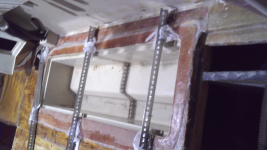
20210703_195946.jpg
4 of the 6 stringers are merely 2x4's laminated over and tabbed to the hull.


20210703_201004.jpg
The basic design throughout. Low profile 2x4's.

20210703_200955.jpg
As shown, some sections had already seen some major stress and were stress cracked because they were so rotted in some spots.

So what do to his think, stick with the same stringer sizing and design but improve the lamination schedule and quality of it? Or try to beefen them up some or make them a little more substantial?
 

kcassells

Fleet Admiral
Joined
Oct 16, 2012
Messages
8,738
Speaking of my floor coming up, how's your rebuild coming along!?

I definitely took 1,001 measurements with pictures. My little girl was getting tired of holding the camera we took so many, haha.
Yes you will want to use 3/4" exterior grade ply. Not "treated" wood but exteriror rated. From hull to underdeck side height. These boats have quite a few underdeck stringers and crossmembers.
Looking real good you are!
Not sure if you did but save the live well and side wells and they can be reused later in the biuld.
My ply stringers were elcrappo! literally still had worms in the wood.
Today pulling some wire, add1 more deck access hatch to bilge and fiddle with bilge pump/wiring. Finally looks like a dry day here.

1625397819698.png
 

kcassells

Fleet Admiral
Joined
Oct 16, 2012
Messages
8,738
The exterior grades from best to acceptable are;
AC, BC,CD, basically that represents the number of possible voids in the wood. Then of course their are all the composites out there that will cost you lots of ching ching.
 

WalleyeSniper

Petty Officer 2nd Class
Joined
May 15, 2018
Messages
108
The exterior grades from best to acceptable are;
AC, BC,CD, basically that represents the number of possible voids in the wood. Then of course their are all the composites out there that will cost you lots of ching ching.
Yep, we just bought a couple sheets of 3/4" AB marine ply $$$, and a few sheets of 1/2" marine ply. The 3/4" was 7 ply and the 1/2" was only 5 ply. But, they'll do the the job!

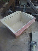
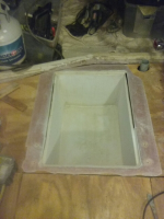
I definitely saved the in floor fish boxes and the hatch openings. They were all flawless and sealed still. The floor was actually in amazing shape, still completely sealed and dry wood throughout. Had I known that, I would've cut safer and saved it lol. Oh well.

These in floor fish boxes are 48" long by 15" wide. When I seen prices on replacements, I decided to keep them, hahaha.

I still don't know if should stick with the meager 2x4" stringer design they had, or if I should make them more substantial and beefier/taller. In the pics above you can see how short so many of them are. I'm assuming that's for clearance for the fish boxes, but I feel like I could still use 2x6's and still have a couple inches clearance. What are your thoughts on that?

Your build is looking awesome!!!! Do you have a thread for your build so I can keep up with it and tag along for the journey!? It's looking killer.
 

kcassells

Fleet Admiral
Joined
Oct 16, 2012
Messages
8,738
Yep, we just bought a couple sheets of 3/4" AB marine ply $$$, and a few sheets of 1/2" marine ply. The 3/4" was 7 ply and the 1/2" was only 5 ply. But, they'll do the the job!

I definitely saved the in floor fish boxes and the hatch openings. They were all flawless and sealed still. The floor was actually in amazing shape, still completely sealed and dry wood throughout. Had I known that, I would've cut safer and saved it lol. Oh well.

These in floor fish boxes are 48" long by 15" wide. When I seen prices on replacements, I decided to keep them, hahaha.

I still don't know if should stick with the meager 2x4" stringer design they had, or if I should make them more substantial and beefier/taller. In the pics above you can see how short so many of them are. I'm assuming that's for clearance for the fish boxes, but I feel like I could still use 2x6's and still have a couple inches clearance. What are your thoughts on that?

Your build is looking awesome!!!! Do you have a thread for your build so I can keep up with it and tag along for the journey!? It's looking killer.
Fhttps://forums.iboats.com/forum/boat-repair-and-restoration/boat-restoration-building-and-hull-repair/8464424-rehab-sportcraft-222-1983-deep-v-hull-cuddy-walkaround..inzee

the studs they have minimal structural value compared to ply. Alot easier but whatever you choose it's your boat.
 
Status
Not open for further replies.
Top