Re: 1985 Force 125 no spark on coils 2 and 4
With the trigger resistance within range that is a good sign. I understand you tried switching the orange wire from the CDM's, i.e. from #1 to #2 and was able to see positive spark on #2 and had the same positive results with #3 orange wire to #4 cylinder. With the preceding testing or switching of orange and red wires, it proved and tested ignition coils are all properly working.
Another component you can eliminate is the stator. Since only a pair of wires (yellow and blue wires) feed each CDM, and both CDM's are getting powered as indicated by the spark on #1 and #3, it means power from the stator is good. And thus the diagnosis only leaves three major components, trigger, CDM's and wiring.
Resistance check on the trigger and also voltage output seems to be positive (except for #4). Which if we only focus on #2 cylinder for now, means that the only component left to be diagnose and tested is the CDM and associated wiring. CDM's have single power source provided on the yellow and blue wires from the stator. However, inside there are two separate ckts which are fed by two separate trigger signal ckts (2 pair of wires) timed by the magnet orientation in the flywheel. It is not unusual that one ckt will die separately from the other ckt although both are housed on the same CDM component. And since this CDM is sealed, there is really no way of diagnosing except through process of elimination using known working component.
Now, since you know for a fact that the #1 ckt on the #1 CDM (feeding both #1 and #2 cylinders or coils) is working when you switched the orange coil wire to #2 and had positive spark, you should also be able to validate the #2 ckt on the #1 CDM could be faulty if you switch it over (the red coil wire) to #1 cylinder coil. If you see no spark then it is an indication the #2 ckt (on #1 CDM) could be bad. SWITCH BACK THE ORANGE AND RED COIL WIRES BACK TO THEIR ORIGINAL CONFIGURATION BEFORE THE NEXT TEST.
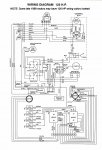
But then there is also the question of the trigger signal feeding the #2 ckt (in #1 CDM). To validate this you will need to switch the pair of trigger wires feeding each ckts in the #1 CDM, i.e. OR & GRN with RD & WH-GRN. YOu do this in the terminal board located in the engine cowling. NOTE: YOU SHOULD BE DOING THIS TEST WITH ALL PLUGS REMOVED FROM THE CYLINDERS BUT ALSO GROUNDED. THIS TEST CAN CAUSE A SERIOUS BACKFIRE THAT COULD CAUSE DAMAGE TO THE INTERNALS OF THE ENGINE.
With the trigger wire pairs switched, it means the timing of trigger signals between #1 and #2 cylinders is way off and could cause back fire so make sure you are doing this test with the plugs off or removed from the cylinder or just use spare plugs wired ground to the engine body. Since you've already proved there is 0.5V+ on the #2 trigger wire, you should see sparks on #1 plug since you already validated the CDM's #1 ckt, coils and wiring are all working. If there is spark on #1 it tells you the trigger signal for #2 is working. And if there is no spark on #2 it tells you #2 CDM ckt is bad (anD this is because you already proved the trigger signal for #1 is working) and the CDM needs to be replaced. However, if there is no spark on #1 it tells you the trigger signal from #2 is bad or not working. And if there is spark on #2 it tells you the CDM's #2 ckt is good. If there is no spark on neither #1 or #2 it tells you the trigger signal for #2 and the CDM's #2 ckt are both bad. THIS DOES NOT NECESSARILY TELL YOU THE TRIGGER IS BAD IT COULD ALSO BE THE MAGNETS UNDER THE FLYWHEEL WHICH YOU SHOULD ALSO INSPECT AS A PART OF THIS TROUBLESHOOTING.
CAUTION - Make sure remove all plugs and are grounded properly. Disconnect the white wire from each CDM coil from the engine terminal board to ensure the kill switch doesn't affect the testing and diagnosis. The disconnected white wire should be taped temporarily and lifted from ground.
You can do the same troubleshooting with #3 and #4 although you might want to validate the #4 trigger signal output voltage first.


