Re: 1988 OMC Ballist resistor location??
It shouldn't matter.
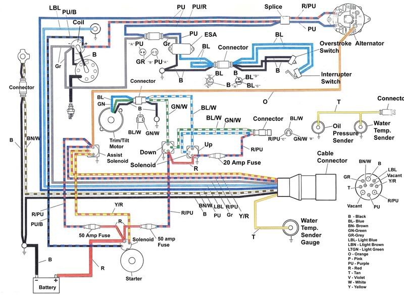
If you look at the circuit diagram, you'll see that the A+ (thru the ballast "resistor") goes directly to the "plus" side of the coil.
The ESA (output) is essentially in parallel with the points/condenser.
The ESA using an electronic switching transistor and associated electronics "shorts" out the points/condenser circuit to briefly stop ignition (it actually "pulses" it) to cause momentary torque "pulses" to allow you to easily pull it out of gear.
The gray wire that goes from the ESA to the NEG coil lead & dist also goes directly to the tach.
(by the way, the instrument cable diagram in my OMC manual shows the tach wired wrong....they have the gray, dark blue, black and purple wires all connected to the same "lug" on the tach! An obvious huge error that would blow fuses and/or cause fireworks!!!
All this works great with mechanical points. If you use an electronic ignition like Pertronix or some other electronic ignition like MSD etc, you must have some sort of isolation to prevent ESD/electronic ignition system interaction. Pertronix does it with a diode/resistor combination. I'm sure MSD does a similar circuit.
If you install an MSD, Pertronix or similar system just follow their directions with the "ballast" wire. Some may tell you to remove it and others may just have designed theirs to keep it in place.