Re: 1993 Force 150 tilt / trim repair
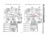
Can you post an illustration on how the current relays are wired? I would surmised the control ckt for the relays is already as shown in schematic "to trim relays" with the blue and green wires for up and down control. the other two wires could just be ground wires (brn/wht and tan) for the relays but need to verify first. Unless these two wires (brn/wht and tan) are hot or power wires, then it could the be it is for the load ckt of the relays what actually powers the T&T motor. If they are not hot or powered wire but instead just ground wire for the relays, then the relays load ckt will come straight from the starter solenoid the same terminal where the 20 amp fuse is connected.
Yeah Jiggz, thats the same diagram as in my FSM. It shows all the wiring for the T/T control circuits (i.e., switches), but it doesn't show the wiring that carries power from the battery cables to the T/T relays. That is covered in the diagram I posted above.
Thanks for taking time to help.
Can you post an illustration on how the current relays are wired? I would surmised the control ckt for the relays is already as shown in schematic "to trim relays" with the blue and green wires for up and down control. the other two wires could just be ground wires (brn/wht and tan) for the relays but need to verify first. Unless these two wires (brn/wht and tan) are hot or power wires, then it could the be it is for the load ckt of the relays what actually powers the T&T motor. If they are not hot or powered wire but instead just ground wire for the relays, then the relays load ckt will come straight from the starter solenoid the same terminal where the 20 amp fuse is connected.


