1998 115 Evninrude E115SLECM Testing the Rectifier

c6mcfall

Petty Officer 2nd Class
Joined
Jun 19, 2013
Messages
100
I'm not getting a tach reading and none of my guages are working. Motor starts and runs, I took my meter, put it on diode test, connected one lead from the MM to yellow wire pins in the connector, other to the red lead coming out of the rectifier. For both yellow leads I got 393 reading on the MM. When I reverse them I get OL. When I go from the red wire to the tach wire I get only 12ohms.

I thought that doing the diode test I should see readings going both directions or is that not the case?

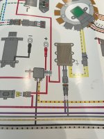
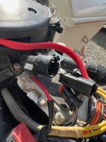
IMG_8249.jpg IMG_8250.jpg
 

c6mcfall

Petty Officer 2nd Class
Joined
Jun 19, 2013
Messages
100
Right, and I went back and tested it again. From the red lead coming off the regulator and it does block in one direction, then tried it from ground and it blocked in one direction. How about the tach, how do I test the tach lead coming off the regulator?
 

Vic.S

Rear Admiral
Joined
May 4, 2004
Messages
4,720
Right, and I went back and tested it again. From the red lead coming off the regulator and it does block in one direction, then tried it from ground and it blocked in one direction. How about the tach, how do I test the tach lead coming off the regulator?
Carry out the tests below snipped from the CDI Electronics Trouble shooting guide

Regulator/Rectifier Bench Tests

1. Diode plate check: With all wires disconnected from the regulator/rectifier, using a meter set on its Diode scale, test the diodes from each of the two battery charge wires/terminals (typically Yellow wires/terminals) to the Red wire/terminal. You should get a reading one way but not the other. Check the resistance from each of the Yellow wires/terminals to case ground. You should have a high reading, typically in the M range. The Red wire/terminal should not read to ground, but may show a very high reading (25M ohms or more).

2. Tachometer Circuit: With all wires disconnected from the regulator/rectifier, check resistance between the Gray wire and engine ground. You should read approximately 10K (10,000) ohms. Both (Gray to Red) and (Gray to each of the Yellow) wires should be a high reading, typically in the M range.

Also. Check the blade fuse associated with the wiring harness.
 

c6mcfall

Petty Officer 2nd Class
Joined
Jun 19, 2013
Messages
100
Thanks Vic. So here are my results

1. Diode plate check: On the diode scale, going from the red wire to the yellow I get a reading one way. Same with ground to the yellow, although the numbers are not the same from yellow wire to yellow wire (both red wire and from ground) On the ohms reading I get 1.2M ohms on one yellow and .2M ohms on the other

2. Tach Circuit test I get 10.5K Ohms on Gray to ground. Grey to Red .3M ohms; Yellow to Grey both read 1.72 M ohms.

Checked the blade fuse and it's fine.
 

c6mcfall

Petty Officer 2nd Class
Joined
Jun 19, 2013
Messages
100
I did reconnect everything back up and my tach worked, engine ran didn't notice anything out of the ordinary. But when I went to disconnect the battery the positive side was super hot. I did buy a new rectifier and when doing the tach test above I got 1.7M ohms, vs 10.5K ohms on the original (27 year old) rectifier. New one installed but off to the next problem
 
Top