2001 Mercury 115HP EFI 4 stroke tachometer not working

Zippady

Cadet
Joined
Jan 2, 2020
Messages
23
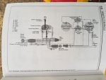
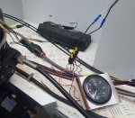
The tacho hasn’t worked since I own the boat, while I’m fixing some other things this is another project I want to fix up but I have run into issues and I’m not sure if it isn’t working because of a bad setup or something broken. Into the back of the gauge on the send pin I have both a grey wire and a brown and white wire. There is also a light brown wire with blue stripe that isn’t connected to anything. At the remote control (outside the unit) I have a green / white, red, brown, blue white.

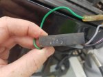
initially I brought a generic gauge and did a direct swap but that didn’t change anything, my manual listed a tacho converter module which I can’t see so I brought one of those, but looking to install it the colours don’t line up.

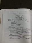
So now I have the original tacho in unknow condition, a new generic tacho and the tacho converter module with coloured wiring which doesn’t line up with what my manual says (manual says green is the tach signal)

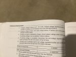
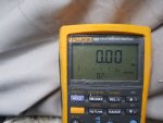
What is the output am I looking for to identify which is the signal wire? Is there some voltage or frequency I can identify with a multimeter? I’d rather not just start trying random wires and fry either the tacho or the converter module.

Yes the outboard is charging the battery with the rectifier putting out 14v
 

Zippady

Cadet
Joined
Jan 2, 2020
Messages
23
Ok looks like I read the manual wrong and confused gray for green, I’ll give the gray wire ago tomorrow.

i’m still interested to know if I should be able to measure a signal from the gray wire to check it is working if the gauge doesn’t show anything
 

Zippady

Cadet
Joined
Jan 2, 2020
Messages
23
Still not fixed but I have made progress. I had so far been looking at the Seloc Manual because it has a more complete wiring diagram however, it made it look like the tacho module is at the gauge end. The Mercury Manual only shows it in the test procedure but makes it look part of the loom so I went looking and found it at the motor end under the fuse cover.

once I found it I was able to conduct the test procedure which passed. I did a continuity test on the gray wire at the motor to the back of the gauge and it doesn’t appear to have any breaks in it. Because I couldn’t think of anything else I plugged the generic gauge straight into the module at the motor and run power straight to the board with no luck (the needle on both gauges make a small movement down when power is turned on).

while the batteries have been charging I did check the voltage while on charge more closely and it was at 14.5v. The test procedure for the regulator rectifier says to replace the regulator if the output is 14.5 to 15.0 volts so I guess I’ll replace that as well.

Does the regulator / rectifier out putting 14.5v indicate any problems?
 

Attachments

  • photo325191.jpg
    photo325191.jpg
    230 KB · Views: 12
  • photo325192.jpg
    photo325192.jpg
    396.1 KB · Views: 13
  • photo325193.jpg
    photo325193.jpg
    380.1 KB · Views: 7

Zippady

Cadet
Joined
Jan 2, 2020
Messages
23
I’m not sure about the tacho, I asked the shop and took their word, it is one of these

https://www.boatingandrv.com.au/kus-tachometer-6000rpm-and-digital-hourmeter/

I’m not really sure about the inner workings of the regulator which lead to a high voltage but if it might damage the batteries I figure a $100 regulator might save 2x $200 batteries and a bad day on the water. I’m basing the replacement on this page
 

Attachments

  • photo325250.jpg
    photo325250.jpg
    400.7 KB · Views: 4

sam am I

Commander
Joined
Jun 26, 2013
Messages
2,169
So on that engine (the 4 stroke 115HP EFI), the tach sig originates from the ECU and not the rec/reg like our old school engines some of us have and are used to trouble shooting. So it's digital in nature and origin. I don't have one so i'm only going by what I can glean off the inter-webs/merc's service info.

That "tach signal converter" changes the nature of the signal in some way shape or form, not sure if it is a freq divider, up converter, filter, etc, etc, and its appears to require a power source (12V purple wire) to achieve this "conversion", so its an active device (perhaps with passive components as well)..........wish I had one to test, however!!

Lets call it (the converter) a gizmo/black box for now, we know a few things....
  1. We have a ECU that generates our tach signal, its most likely digital, it's most likely 0-5VDC or 0-12VDC (serial pulse square wave looking signal).
  2. We have a black box this digital tach signal goes into and out of that is active/requires 12V and ground.
  3. Your tach requires some sort of signal (and 12V and ground) to work..
To test, I'd make sure....
  1. I have 12V and ground on both my converter and tach.(else fix)
  2. A signal going into and out of the converter with the engine running, ya might need a o-scope. (else replace)
The manu of the tach states in their advert these type sensors 1 and 2 work (one of which says = to or > 5vp[o-scope], see specs on sensors) with the tach, so based on the those types of sensors and their sig outputs, the signal requirements aren't too crazy (like 60V or something), I'd think/guess then the stock merc converter should be compatible...

My guess, with signal in present, is the "tach signal converter" is bad (or not getting power)..........

If power and signal in are okay but converter bad, try to remove the converter all together!! From the looks of it, bet that tach would run direct off the ECU signal (converter signal in), just adjust/cal the tach "speed ratio" to your motor.
 
Last edited:

The Force power

Commander
Joined
Feb 3, 2019
Messages
2,350
So on that engine (the 4 stroke 115HP EFI), the tach sig originates from the ECU and not the rec/reg like our old school engines some of us have and are used to trouble shooting.

Thanks for jumping in...this stuff is too Hi-tech. for me (I'm old & simple):stupid:
 

sam am I

Commander
Joined
Jun 26, 2013
Messages
2,169
I'm old & simple

Hardly!!...........We just don't live and breath this stuff and I just simply make it up as I go along :tea:


I figure a $100 regulator might save 2x $200 batteries and a bad day on the water.

Your reg is working fine, 14.5 is perfect!! BTW, I know this is TMI but! You have a 3 phase charge winding on that engine that runs a Shindengen rec/reg........VERY descent setup!! Should outlast us all and I have noted that the Shin reg's run up at 14.5 which is the norm for these units.

I tested Shin's single phase FET type rec/reg's on my old Merc a few years back, they run much cooler then the ole Merc stock stuff but, they didn't like to be ran in parallel with each other as the old stator's has two sets of charge wingings that make up a 40 amps total setup, with two in parallel, my voltage was running up around 16'ish volts so I went back to the ole hot stock stuff.
 
Last edited:

Zippady

Cadet
Joined
Jan 2, 2020
Messages
23
Good news on the reg, thanks sam am I

i found a better wiring diagram that’s shows you are right and that the green wire from the tacho converter is going to the ECM. From your suggestions above since I have a new tacho converter (you can see the second one in the above photo sitting on the fuse panel cover) at this stage I think I’ll focus on checking the signal on the green wire coming into the tacho converter and the tacho itself.

i’ll break out the good multi meter to try and measure a signal coming out of the green wire, I don’t have a scope but might measuring frequency tell me something if I get nothing on AC or DC? Or do I need an AC voltage to be measureable for frequency to show anything?

The converter passed the test in the manual which I’ll post below but I was grounding the meter on the engine block so I will check the ground like you mentioned.

The wrecker doesn’t have a mercury gauge which is why I got the generic one it I have seen a similar age two stroke gauge on Facebook so I might see if it is still around to go and have a look if they are the same
 

Attachments

  • photo325304.jpg
    photo325304.jpg
    420 KB · Views: 6
  • photo325305.jpg
    photo325305.jpg
    385.9 KB · Views: 5

sam am I

Commander
Joined
Jun 26, 2013
Messages
2,169
Good news on the reg, thanks sam am I

Cool! and glad I could help!!

I don’t have a scope but might measuring frequency tell me something if I get nothing on AC or DC? Or do I need an AC voltage to be measurable for frequency to show anything?


AC settings and most likely will be dependent on the meter's bandwidth if ya can see something meaningful.....

If the meter has a frequency measure setting use that, these by default and typically, using the frequency measure setting, usually can read and are spec'd as slow as 0.5/1Hz and up to 200khz w pulse width > 2us. You'll be down near at 800RPM =13.33RPS = 13.33Hz = 13.33 C/S (cycles per second). This should work!

Freq * 60 = RPM

On these same higher end DMM's mentioned above BUT, on their AC voltage setting, they usually only do as low as 45hz and up to 5khz/20khz. Not sure this setting will register much unless you're up near 3000RPM.

The above is typical of a Fluke 87 and the like.....

If the meter doesn't have a frequency measure setting, You're back to using Its bandwidth in its AC measuring setting and this is typically 45hz-1khz. This type obviously might not work so well like and is similar the high end type on their AC voltage setting.

This is typical of a Fluke 77 and the like..
 
Last edited:

Zippady

Cadet
Joined
Jan 2, 2020
Messages
23
I have a Fluke 189 from a previous short lived career many years ago so it is probably more capable than me

i brought the boat home to work on today but then it rained all day so it wasn’t very productive, I did go out during a small gap and used on some bullet connector test leads I made so I could check the input and output on the tacho module. To start off I check the purple and black going into the module and was very unhappy to find no voltage going into the module which throw my plan, because of that and the rain a checked a couple of other quick things and went back inside. It was only after I was back inside and dry did I remember that the fluke has manual settings for AD or DC instead of auto select like the other meter I was using and I had it set to AC trying the read the DC power voltage........guess I’ll try that one again tomorrow.

the other thing I did look at though was the green input wire which is the signal from the ECU to ground. All I got was 0.2 volts AC which I guess is just noise and 0Hz

I’ll have a look and see if there is anyway to directly check the tacho signal output from the ECM itself, the plug going into the ECM doesn’t look like I could get a meter onto it but maybe somewhere else
 

Attachments

  • photo325375.jpg
    photo325375.jpg
    366.6 KB · Views: 0

sam am I

Commander
Joined
Jun 26, 2013
Messages
2,169
Nice meter, got the 289 myself........

Well not to belabor this,

The spec on the 189's AC voltage setting says +/- 2% @ 20hz. so idling at 800RPM/13.33hz you MIGHT see something BUT, that spec is probably given with a sinusoidal wave form NOT a pulse DC waveform, wouldn't trust it, HOWEVER.....

The Freq counter setting on that meter should be good to go and should have some intelligible readings even with pulsed DC and down to 0.5hz.......So with the motor running, measuring the converter signal in (ECU out) AND to a good ground AND around at 13hz, I'd expect to see more then your reported "0hz". Hmmm,

This doesn't look good, even with the converter powered or not, with engine running, the tach signal in should be wiggling around some.

I seemed to recall some time back someone else here having this same issue with this same/similar motor as yours....

Find that by clicking HERE , think my light bulb came on (growing dimmer seems again) in #14 as to the ECU being tach sig source

in #24 he says ...

"1 volt (AC using DVA) on grey signal output wire"
"1 volt (AC using DVA) on grey signal output wire confirmed at tachometer"

Hmmmm, this seems too low.......DANG!, I wish I had one of those "converters" to test.

BTW and total side note, when using a DVA adaptor, the meter has be set to DC.......This is due to that the meter reads a cap that charges up to some peak DC value.


Just for grins, I'll put my 289 on a sig gen this morning after b-fast and see how well (and low, 10hz'ish say) the freq counter works with a narrow'ish pulsed 5/12v DC waveform.
 
Last edited:

sam am I

Commander
Joined
Jun 26, 2013
Messages
2,169
So a 10hz pulse (2.5Vp, zero DC offset, 10% duty cycle[10ms wide]) on the 289 (same'ish as yours), frequency setting measures 10hz (duh) at 0.78Vrms on the AC voltage setting.

I'm guess the ECU is putting out something very similar and even higher in amplitude. Your 189 should have seen it easily on both setting AC Voltage or Freq.

So I was thinking on this a bit, not like headache level thinking or anything like that, well almost BUT! I bet as a work around for the ole dreaded Dead ECU Tach Output Syndrome (DE-TOS), why not just hook the tach up to the stator like we did back in the boomer? You know, if it happens to go down like that or something...........

Click image for larger version  Name:	115 hp.jpg Views:	1 Size:	427.2 KB ID:	10834022

12 pole (6 pulse per rev) stator, the tach will (should) get its sig ground ref via the rec/reg's ground......

See #6 above, hook the tach's sig in the any of the stator's white output wires. WTH.....should work eh?
 
Last edited:

Zippady

Cadet
Joined
Jan 2, 2020
Messages
23
I already checked to see if I have an unused gray wire at the regulator so if the whites do the same thing I’m open to that. Just a matter of making a T connection in any of the white wires, put a 1 amp CB on the new line and connect it into the gray wire to the dash in place of the output from the tacho converter module?

i also noticed there is another green wire coming out of the ECM next to the tacho signal green wire heading to the main relay but I can’t find any info about what is on it. Do colours mean they might be the same signal or do they just run out of colours?
 

sam am I

Commander
Joined
Jun 26, 2013
Messages
2,169
I already checked to see if I have an unused gray wire at the regulator

Wrong type (manu) of reg, I've not seen any Shindengen's have a tach output,


so if the whites do the same thing I’m open to that.

More or less, yes cept the white wire/s directly connected will have no "conditioning" per-se............

HOWEVER, most off the shelf tachs will live happily ever after connected there and are designed such that their inputs are pretty robust....just have to check it out with your particular.

When you Cal the tach, use your 189, Freq * 60 = RPM. I'm not exact on the waveform output of that 3 phase winding, however......

Running 12 poles (given by Merc)....

360 degrees/6 pulses = 60 degrees/pulse

with 3 phase stator windings (given by Merc) fixed at....

360 degrees /3 phase = 120 degrees /phase (assuming/typical)

Therefor, the windings wiill produce 2 pulses for every 120 degrees the stator rotates

2 pulse/120 degrees = 6 pulse/360 degrees (eq. 1)

and

360 degrees = 1 rev (eq. 2)

sub (eq. 2) into (eq. 1)

6 pulse/rev!!! Wahla!!

Moot point for 3 phase, should cal up just like any ole 6 pulse per tach!!

Just a matter of making a T connection in any of the white wires, put a 1 amp CB on the new line

Yes and yes, a inline CB/fuse is a good call.


and connect it into the gray wire to the dash in place of the output from the tacho converter module?

Yes, remove the converter altogether, trash it!!

If in fact the ECU's tach output is dead to the world, I suspect the converter is killing the ECU's output driver......Sad design/s around the board if this is truly the case.

i also noticed there is another green wire coming out of the ECM next to the tacho signal green wire heading to the main relay but I can’t find any info about what is on it

Hmmmm, not sure either but, I haven't really looked to know forsure


Do colours mean they might be the same signal or do they just run out of colours?

Usually yes but, seems this type of engine and its wiring has very random colors, looks like someone was eating Skittles on that design day.
 
Last edited:

sam am I

Commander
Joined
Jun 26, 2013
Messages
2,169
wish I had one to test

Just bought a new converter......I HAVE too see what Merc charges $30 for.

Any bets, component wise, it's less than $1? And at that, it's possibly a ECU sig out killer! DANG, such good bargain for $30+

Oh well, such are the prices we pay to have fun I reckon, R&D was working lots of O/T here no doubt, totally justifies the cost of extra fine(beta?)designs.

Wondering thou, perhaps there are revisions?

Zip, do you see perhaps revision suffixes (alpha and/or numeric) on the two parts? The old converter verses your new converter, are there any part number changes from one to the other?
 
Last edited:

Zippady

Cadet
Joined
Jan 2, 2020
Messages
23
I've only got the new one here but I'll get the old one next time. The new one has nothing at all on the black box but the green wire does have a tag with

3/28/2018
8M0026570 ID-P7

which make it 17 years younger than the outboard if that is a manufacture date
 

sam am I

Commander
Joined
Jun 26, 2013
Messages
2,169
That "ID-P7" suffix I think might indicate a rev.........Hmmm, not sure, yes plz, let me know if the old one has markings, ty.
 

sam am I

Commander
Joined
Jun 26, 2013
Messages
2,169
Ch 1/top = in
Ch 2/bottom = out

bewFile1.jpg


A 12V inverter??.....geeesh and here I though $30 would be have at least been perhaps a slight bit more exciting.
 

Zippady

Cadet
Joined
Jan 2, 2020
Messages
23
Can you explain that test to me? Are you inputting 2v and it is outputting 5v?

i checked the original module and it has a part number stamped on it but is rubbing off and is hard to read. It looks like 17451A, I can’t find anything with that but I found a 1746A3 and 17446A11 both of which look like the same black box with different configurations of wires going in.

The parts manual actually says I’m meant to have a 56-883040A 1 instead of the 8M0026570 I brought, but I’m not concerned because the ECU output was already gone before I plugged it in and they look identical.

If the price of the some of these parts is upsetting, you probably don’t want to here that I’m probably going to spend $45 on a rectifier test harness. With the plan to take a tacho signal from the stator I had a look at where I could get access. All the white wires have some temperature or physical protective sleeve on them and in general I’m not confident in chopping into the loom so if I get the test harness I can seal the two unused wire and use the third T piece to plug a bullet connector in and run the signal down to the gauge.
 

Attachments

  • photo325712.jpg
    photo325712.jpg
    227.5 KB · Views: 1
  • photo325713.jpg
    photo325713.jpg
    236.5 KB · Views: 1
Top