2001 Mercury 115HP EFI 4 stroke tachometer not working

Texasmark

Supreme Mariner
Joined
Dec 20, 2005
Messages
14,784
Still not fixed but I have made progress. I had so far been looking at the Seloc Manual because it has a more complete wiring diagram however, it made it look like the tacho module is at the gauge end. The Mercury Manual only shows it in the test procedure but makes it look part of the loom so I went looking and found it at the motor end under the fuse cover.

once I found it I was able to conduct the test procedure which passed. I did a continuity test on the gray wire at the motor to the back of the gauge and it doesn’t appear to have any breaks in it. Because I couldn’t think of anything else I plugged the generic gauge straight into the module at the motor and run power straight to the board with no luck (the needle on both gauges make a small movement down when power is turned on).

while the batteries have been charging I did check the voltage while on charge more closely and it was at 14.5v. The test procedure for the regulator rectifier says to replace the regulator if the output is 14.5 to 15.0 volts so I guess I’ll replace that as well.

Does the regulator / rectifier out putting 14.5v indicate any problems?

Voltage from running the engine starts being recorded at 1000 RPMs and increases to WOT...in the manual. At WOT with a full battery, a non regulated alternator will put out up to 16ish volts while a regulated one will be up to 14.5v. I used Seloc and Merc OEM manuals on my last engine and did find Seloc to fill in some blanks left by the OEM manual.

Before you plunk down cash for a regulator look up the RPM vs voltage output in the manual and remember this is for a battery with a reasonable charge, keeping the amperes within the specified 9-16 Amperes rating for your particular engine.

Tachs can croak. My last boat was a 2002 and the Merc tach was working fine. Current boat is also a 2002, Merc, and the Farina tach had croaked. They do fail. You need 3 things for it to work so ensure that you have all 3...(Ignition) switched power, (Red/Purple stripe, or Purple), Ground (Black) and Tach Input (Grey). The other wire (Green?) is for your light bulb.
 

sam am I

Commander
Joined
Jun 26, 2013
Messages
2,169
Are you inputting 2v and it is outputting 5v?

Yeah sorta of.......The scope has multiple traces (4, only 2 shown) that each can be set independently to read some xx voltage per division (See scope's screen, the horizontal lines running from left to right account for 8 total divisions from top to bottom).

The top trace(sig in) is set on 2V/Div, so the signal in is about 2.5V and the bottom trace (sig out) is set on 5V/Div, so the sig out is about 12V.

The module is just an logic inverter (74C14) and is most likely totem pole output with current buffering, and finished with just a sprinkling of hysteresis for noise immunity

It has a minimum input logic level of say 2V for a high, so when it sees 2V or higher on its input, it outputs 12V. Then when it sees less then 2V on its input, it puts out 0V. All of which is inverted low in = high out, and high in = low out.

It looks like 17451A, I can’t find anything with that but I found a 1746A3 and 17446A11 both of which look like the same black box with different configurations of wires going in.

Weird, okay ty

The parts manual actually says I’m meant to have a 56-883040A 1 instead of the 8M0026570 I brought,

Hmmm, wonder if there's a difference electrically?

but I’m not concerned because the ECU output was already gone before I plugged it in and they look identical.

It appears you're not alone, I see posts out there where it also appears the ECU crapped out on the tach out.

That really should not have been able to have happened in the normal course of use and life, those ECU outputs should be bulletproof...Sad design if the converters are taking it out somehow.

If the price of the some of these parts is upsetting, you probably don’t want to here that I’m probably going to spend $45 on a rectifier test harness.

Think maybe I'm just too cheap


With the plan to take a tacho signal from the stator I had a look at where I could get access.

Understandable, this is new territory and I think we're cutting new trail!!


get the test harness I can seal the two unused wire and use the third T piece to plug a bullet connector in and run the signal down to the gauge

Agreed
 
Last edited:

Zippady

Cadet
Joined
Jan 2, 2020
Messages
23
Before you plunk down cash for a regulator look up the RPM vs voltage output in the manual and remember this is for a battery with a reasonable charge, keeping the amperes within the specified 9-16 Amperes rating for your particular engine.

I haven’t order a regulator, my main concern was a $100 reg damaging two $200 batteries but from all the comments here I’m happy to stick with it
 

sam am I

Commander
Joined
Jun 26, 2013
Messages
2,169
Few note worthy things that might help....

You'll most likely use your Fluke to cal the tach, as such, just multiply the flukes freq reading while measuring the stator's white signal wire by 10 (not 60 as stated above, that was incorrect for a 12 pole stator, apologies), use that result to adj the tach to match.

Freq * 10 = RPM

For the math'ies...........

Given a 12 poles stator = 6 pulses per rev = 6 P/R (eq. 1)

If the desired RPM to cal the tach at is 800RPM (R/M), then 800/60 = 13.33 rev per sec = 13.33 R/S (eq. 2)

from above, (eq. 1) * (eq 2) where P/R * R/S = P/S (R's cancel) = pulses per second = cycles per second = Hz

So with that, 6 P/R * 13.33 R/S = 80Hz

If life (or the tach) is linear then

800PRM/80Hz = 10

Freq * 10 = RPM,

Again, this is assuming linearity and you can just simply multiply any freq reading by 10 for the appropriate RPM.

This only applies to a 12 pole stator.


Additionally the manu stated the following about their (your tach)


Notice :
In some place where there is heavy tacho signal disturbance, the pointer of the tachometer may not move along with the changing of
the rotate speed. Please add a resistor between 1/4-1W, 1-20K in series connection to strengthen the signal processing capability.
We suggest adding a 20K potentiometer in series connection to test.


81WBtPk7xJL._AC_SL1500_.jpg

You may need to do this, not sure
 

Zippady

Cadet
Joined
Jan 2, 2020
Messages
23
Thanks, I’m waiting for the harness to come in so I’ll grab a potentiometer while I wait just in case

my current plan is to test the signal with the fluke, then the new generic tacho to make sure it doesn’t over voltage or cause any issues on a day out. If that works I’ll try the original tacho again. I’m hoping the original still works if it is just the ECU output not working so it matches the other gauges
 

sam am I

Commander
Joined
Jun 26, 2013
Messages
2,169
I was thinking, again............

If need be, we might get away with using that new converter for noise and buffering........I'm assuming Merc used it for just that purpose as well. If the ECU was 5V logic, they use it to level shift 5V in to 12V out as seen above, BUT!! I'm fairly certain the logic device they used also had higher current buffering (line driver) and hysteresis (cleans up logic transitions where apps are subjected to a higher noise enviro's, like a motor, go figure).

I'll test mine and see if it can handle say 80Vpp........Requires a series input limiting resistor of course.

Also, begins they suggest a resister might be needed, If you use a pot option, you'll be wiring it as a rheostat, not a voltage divider, right? Just checking......
 

Zippady

Cadet
Joined
Jan 2, 2020
Messages
23
My plan with the pot was to use it to play the with affect of different resistance on the behaviour of the gauge, then when happy buy a fixed resistor of the same value, do I have that logic right?
 

Texasmark

Supreme Mariner
Joined
Dec 20, 2005
Messages
14,784
Sam,

In following along I'm not sure I caught all what you said in that will the 115 4 stroke work with the same tach on the same settings as would a 2 stroke if one were to upgrade his engine to a newer model.....aka digital to analog conversions are internal to the engine........without having to change the tach?
 

sam am I

Commander
Joined
Jun 26, 2013
Messages
2,169
Sam,

In following along I'm not sure I caught all what you said in that will the 115 4 stroke work with the same tach on the same settings as would a 2 stroke if one were to upgrade his engine to a newer model.....aka digital to analog conversions are internal to the engine........without having to change the tach?

Well, not sure exactly how to answer but.........


Will his original tach work? It should signal wise, but can it cal to a 12 pole stator? Not sure, he hasn't discloses if his original tach has any if at all pole (or cylinder) settings..........There is some over lap between poles and cylinder settings on tachs.


As far as digital and analog, read on if you dare.....

His 115's 4 stroke tach's source signal from the ECU is only "digital" in the sense of yes, it does assumingly have a processor managing/generating it BUT! As processed, the tach signal is just periodic logic level pulses (0V/5V or 0V/12V) that change in frequency dependent on the engines rev's....that's it.

With that said and as far as the testing I've performed with the "converter" and its function within the system, the ECU's tach signal and original tach are NOT "digital" per-se in any part of a/the more traditional sense of a digital serial stream of binary words with addressing, data packets and such.

The "converter", contrary to popular belief here and afar, it's NOT converting digital to analog(or vice versa)......far far from it!! It's just a inverter that by default is being fed, and might be also be level shifting 5V pulses as it uses a 12V supply, so by default, it's totem pole output rails are tied too and output approx 0V and 12V.

Pretty much any modern'ish off shelf tach (automotive 8/6/4 cylinder, marine 12/8/4 pole) would work hooked directly to his ECU's tach's output due to the ECU just outputs a simple frequency varying pulse train.

This is how all basic automotive and marine tach's we use and see work, call the signal analog or digital, they just simply require varied freq pulses be it from a coil, a processor, a plug wire, a lego® with a attached magnet spinning about creating pulsing in a near by hall effect sensor, proximity sensor near rotating gear teeth it doesn't matter, just cal (we're used to switches 8/6/4 cyl or 12/8/6 pole depending on our app) them to display what they should read based on the app, see math above....

The "converter" Merc installs, as discovered (the one I bought and tested anyway) is used as best I can tell to just perhaps level shift from 5V -> 12V.

If used, 5V signal is probably on the low side of some tach's required threshold so a/the converter bumping it to 12V doesn't hurt in that it assures more of a definitive signal level for a wider spectrum of tachs of which, also gives even higher hysteresis thresholds........ If in fact the ECU puts out only 5V logic, bumping(converting) up the signal level from 5V to 12V as close to the ECU as possible, also gives the signal more noise immunity in that any noise picked up in the wires remains constant but swinging from 0v to 12V as opposed to 0V to 5V as it runs to it's destination (the tach) improves the signal to noise ratio (SNR).

Also, this "converter" inverts but, who cares? the tach doesn't. The converter is probably also being used as a current buffer (line driver), due do running wires long distances not only picks up more noise, it adds additional capacitive loading and allowing for higher sinking and sourcing currents improves signal integrity.
 
Last edited:

sam am I

Commander
Joined
Jun 26, 2013
Messages
2,169
Wanted to test the converter, thinking it still might be useful because if it can also accept being connected to the stator (not the dead ECU) BUT with a series limiting resistor, it might just come in handy IF NEED BE for it's buffering abilities.

As a test I just used a variable AC 60 hz test sig source, shown as top trace and drove the converter's input (green wire) through 6.8K limiting resistor. Ran two tests monitoring the output (gray wire) bottom trace...

1) Turned the test signal amplitude down till the output (gray wire) more or less was crapping out (pic 1), looks like the converter needs around a minimum of about 4Vp. The stator certainly can do that!!.

2) Turned the test signal up to 80Vp, assuming the stator output voltages won't even come close (pic 2), looks like the converter can see 80Vp through a 6.8K resistor and be just ducky with it.

Click image for larger version  Name:	NewFile1a.jpg Views:	1 Size:	80.6 KB ID:	10837757
(pic 1)

Click image for larger version  Name:	NewFile1.jpg Views:	1 Size:	78.3 KB ID:	10837758
(pic 2)

So, if the stator's signal amplitude stays within the two limits taken above, looks like the converter will run just fine and drive the tach(s) happily ever after......

Merc believed in it, right? They used it to drive their tach!....It might have killed the ECU (un-confirmed of course) though but!! What the heck.,......If used/needed, just have a 6.8K resistor in series between the two just in case it tries to pull something funny with the stator! Probably take a nuke though to hurt those charge windings....
 
Last edited:

Zippady

Cadet
Joined
Jan 2, 2020
Messages
23
It’s Alive!

It has taken me awhile with bad weather and slow shipping but I finally got all the bits and time. In the below video the 189 is on one stator output from the mercury test harness and the gauge is on another in series with a 25k pot set to around 20k.

The frequency on the fluke is jumping around a lot, I adjusted the gauge to read 800 rpm by sight since that is about the average, I’ll go back and set it to six pole from the manual for more accurate results. I haven’t changed the rpm much to see how it responds but after starting it from the front and walking to the back it was still falling so I feel it may be slow to respond, I’ll play with the pot and see if that make any difference.

I missed your last post before this test but I’ll give that config a go and see what I get.
 

sam am I

Commander
Joined
Jun 26, 2013
Messages
2,169
Yeah, the meter was flipping 75'ish-85'ish, so yes 80hz avg, gauge nice and (too?)stable at 800RPM, looks good, congrates!!

So yes as far as too stable, the gauge probably has a s**t ton of input filtering that is typically capacitive so adding too high of resistor valve in series in the input sig wire will create even higher time constants, t = RC.

The higher the "t", the slower (more stable) the gauge/needle will react to sudden changes in freq/rpm AND noises. BUT!! As described, the needle might move too slow!!........You'll have to find its happy space by reducing the resistor just enough, BUT! Not too much else the needle might start be jumping around on ya......**Sorta like the fluke and using the "avg" button feature, it's is just more or less increasing its input "t" value..Same diff.

All is sorta going to be a case by case adjustment, dependent on the stators' noise levels, tach manu designs, etc, etc of course.

So, yes.....

Insert the series "converter" through a 6.8K or something close.....Then hook the meter and tach to its (the converter)output, thinking that IC in the converter is a schmitt trigger(uses hysteresis).

All should settle out and be more rock solid. This should then allow you to reduce the resistor even more if need be to archive a fast enough response without getting too far down *in the mud* with the tach signal and have a jumpy needle.

Cal it there and just leave the converter inline and run it....

* another pesky eng term that when a given sig level becomes so low in amplitude that it become indistinguishable to the overall systems noise (low SNR).

**On your fluke meter you can get it to calm down a bit by pushing the "min max" button until you see the display indicate "avg". Those flukes have very touchie front ends and trigger easily......Stator's are definitely noisy critters.
 
Last edited:

Zippady

Cadet
Joined
Jan 2, 2020
Messages
23
This is where I’m currently sitting and will try it next time I take it out. Currently wired back up to the original gauge in the dash, fluctuates a little more than the other but should be usable.

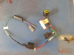
this picture is of what is hooked up, Mercury test lead, un-used connections sealed up, 1amp fused with in line resistor plugging into the input of the converter.

https://youtu.be/VOA_MN6cJX8
 

Attachments

  • photo326659.jpg
    photo326659.jpg
    606.2 KB · Views: 1

sam am I

Commander
Joined
Jun 26, 2013
Messages
2,169
So back the t=RC formula....


Because the input of the Merc "converter" by *default has very very little "C" (capacitance), the "R" (resistance) we've added before the converter (under your heat shrink) isn't now as effective as a filter(lower "t' now). You've noted this and how the replacement was working verses the original.

HOWEVER, because we're, by our design requirements, using that input resistor as a current limiter (recall the limits tests from above where on far outside chance of having 80Vp testing with the 6.8K), we require it, so just leave that there but....

And if desired, add that resistance (your pot) back in series on the OUTPUT of the converter! There you'll be back to more "C" (the Merc's tach's input is probably very similar to the replacement tach you tested with) and adding some "R" back in series via your pot(or discrete resistor, which ever) should get you back with better stability (higher dampening) results due to at least some value "t" needed/desired in our work around design.

* recall that converter was originally spec'd for a nice clean ECU output, not some ole nasty charge winding.

BTW, "t" = time in seconds
 
Last edited:

sam am I

Commander
Joined
Jun 26, 2013
Messages
2,169
Impressive performance. Glad you guys got-r-fixed. Thumbs Up!

You and me both sir!! Wheeew, had my neck stuck waaaaay out on this one! Piece of cake though, right? Had it in the bag from the get go.........lol.

Best now get back to Mad Maxx life, it's safer somehow ;)
 
Last edited:
Top