2002 EFI 115 4-Stroke Tachometer not working

Status
Not open for further replies.

mbhoag

Petty Officer 2nd Class
Joined
Aug 29, 2011
Messages
147
OK, I am pulling what is left of my hair out!.

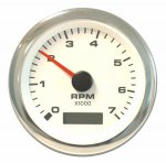
Here is the short version: Tachometer is not working.
2002 115 EFI 4-Stroke Model 115ELPT4S Serial OT540017

With Ignition on (but not started), tach can read slightly above zero, once started, it goes completely to zero.

What I have done to track it down to try and fix...
  • Replaced original Faria Tach with a brand new one (set at 6 poles)
  • With Ignition on (not started) voltage between black/purple at tach is 12+v (DC)
  • Start Engine, voltage between black/grey wire at tach is virtually Zero (A/C)
  • With Ohm meter, checked continuity of grey wire from tach back to connection at motor (it is fine)
  • Verified with meter that Battery IS being charged by system when running
  • Replaced Regulator unit with new one
  • Replaced Tachometer Signal Converter

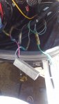
I am guessing because this is a 4stroke, the system is slighly different than those on 2 strokes, which is why this system seems to be wired different. It has one grey wire, that feeds from the engine into a "Tachometer Signal Converter", which outputs the 3 tach leads (grd, power, signal). Not sure how you get 3 from 1... but they do.

Here are my guesses..
  • Since batteries are confirmed to be charging while the engine is running, the stator is fine.
  • Since Tach, Regulator and Tach Signal converter have all been replaced, they are also fine.
  • So I am left with the single grey wire feeding the Tach Converter, how can I test that wire?
What else can I check?
Are there any diagnostic procedures I can use out there specific to this engine?

I appreciate help, this is MADDENING!

Mark
 

mbhoag

Petty Officer 2nd Class
Joined
Aug 29, 2011
Messages
147
Need to check rect/reg

I appreciate that, you may have missed in my post, but I replaced the Regulator, just to make sure... it did not help the issue. That is part of my frustration!
 

Faztbullet

Supreme Mariner
Joined
Mar 2, 2008
Messages
15,930
Just cause its new don't mean its good....test it to see if you have output on grey at motor. Take the old tach you replaced and add a 3ft harness to it and clips to attach to +/- and grey at motor. If it reads rect/reg good and need to look at wire harness.
 

mbhoag

Petty Officer 2nd Class
Joined
Aug 29, 2011
Messages
147
I will test the Grey wire at the motor as you suggested in a couple days (waiting for new impeller to arrive) when I get lower end back on.
 

sam am I

Commander
Joined
Jun 26, 2013
Messages
2,169
I think the problem could be your converter (#17 below) and/or tach aren't getting proper power (ig) and/or ground.....

That particular tach converter (see below) is configured such that its power and ground come from the appropriate tach studs that both the converters wires connects to, hence two of the three wires on the output of the converter that are leading to the tach are actually feeding power & ground back from the tach studs into the converter.

Given the above, make sure that the tach's power stud (I think you checked that stud) and tach's ground stud (0 V) both check good..........

Click image for larger version  Name:	Boatinfo - Mercury Service Manual for 115 hp.jpg Views:	1 Size:	191.9 KB ID:	10602147
 
Last edited:

Faztbullet

Supreme Mariner
Joined
Mar 2, 2008
Messages
15,930
I don't think it has a converter as that's only used on Verado engines to convert digital signal to analog..
 

sam am I

Commander
Joined
Jun 26, 2013
Messages
2,169
I don't think it has a converter as that's only used on Verado engines to convert digital signal to analog..

Not sure, he said he has a 1 wire to 3 wire "converter" inline with his tach and that image came from the 2001+ "Merc 115 EFI 4 Stroke" manual.........Motor runs a 881346T rec/reg, yes

The sig ordinates as pulsed analog if you will in either case but, his/a gauge cluster can be digital or analog, the manual appears to show his/a analog setup running his/this reported "converter" *(#17), perhaps the converter is designed to multiplex the analog sig on top of the converted digital sentences and is a universal, it works for both type setups?....


As per Merc "Tachometer Signal Converter (required for proper tachometer operation)"
 
Last edited:

mbhoag

Petty Officer 2nd Class
Joined
Aug 29, 2011
Messages
147
I do have a converter (see Pic) which I replaced, this is the replacement. I am hoping I can test the input wire for a signal of some sort, and if I have one then maybe the new converter is non-functional itself.

As you can see, it has the signal wire, power and ground all exiting out to the tach. The power and ground wires seem redundant to me however, since power and ground are also fed to the tach via the rest of the gauge cluster, and I have tested both power and ground at the tach to make sure they are good.

But I now am wondering, instead of the power and ground feeding from the converter to the tach, could the power and ground feed from the tach to the converter to power the conversion operation of the signal feed? If that is their purpose then I should also check those wires at the converter itself, not just at the tach... (pulling at straws here)

Thanks for all the help and suggestions! Keep them coming!
 

Attachments

  • photo294566.jpg
    photo294566.jpg
    344.3 KB · Views: 7

sam am I

Commander
Joined
Jun 26, 2013
Messages
2,169
could the power and ground feed from the tach to the converter to power the conversion operation of the signal feed?


Yes, I think I said that but maybe wasn't clear.........The converter is powered via connecting it to the tach's power and ground studs. It's not redundant........The converter appears to require power to work and get its power from hooking it up to the tach's power.

Side note.....TMI, read at your on risk.

If you have a analog tach, which it looks like you do, i have no clue why you'd even need a "converter" in the first place. Which then makes me wonder if this thing is actually an active filter.

I say that because looking up your rec/reg I see it isn't the old school rec/reg shunt type we're too accustom to on our old school OB's. That motor's rec/reg appears to be made by Shendengen, of which, Shendengen developed, sometime ago and uses (in addition to their SCR and FET shunt types) a altogether different technique to regulate magnetos bases alternator outputs.

Motorcycles, ATV's, Snowmobiles, generators, power washers and various battery charging mag (3 phase typically) based engines have been using Shendengen rec/reg's for years now (I ran two in parallel on my 92 175 a few years back) and they're much more efficient then shunt types..... In a nut shell, to regulate charge (not over charge), their rec/reg electronically opens the mag's path to the battery when the battery is full/charged as opposed to shunting(overloaded) it........Mag runs waaaay cooler and last waaaay longer.

At any rate, when I ran the two i experimented with, my tach didn't work worth a crap and now I wondering if this type of rec/reg requires a filter (active) for use with a tach due to its perhaps noisier or something AND that's what we are seeing in your setup......A filter, NOT a digital converter as there is no digital tach on the boat, not that i see anyway.
 
Last edited:

mbhoag

Petty Officer 2nd Class
Joined
Aug 29, 2011
Messages
147
Yes, I think I said that but maybe wasn't clear.........The converter is powered via connecting it to the tach's power and ground studs. .

Yep I read that, but missed the point... you were clear, it was me! :p

As for the TMI... I do appreciate all the info. I am not an electronics whiz and don't pretend to understand all the details of how the rec/reg works, (basic wiring and testing I do understand) but I was making some assumptions about the boat. Namely, that the original tach, converter and the rest of it are wired correctly in the first place.

Here is the original dash cluster and original tach (which I have now replaced), so I have been assuming the converter was also original and needed, even though it has an analog tach...

Even thought I cannot start the engine today (still waiting on impeller), I can run a couple other continuity test on power and ground wires at the converter. Will report back with results.

Thanks!
 

Attachments

  • photo294577.jpg
    photo294577.jpg
    837.1 KB · Views: 3
  • photo294578.jpg
    photo294578.jpg
    455.9 KB · Views: 3

sam am I

Commander
Joined
Jun 26, 2013
Messages
2,169
Here is the original dash cluster and original tach (which I have now replaced), so I have been assuming the converter was also original and needed, even though it has an analog tach...

Wait a tick..........The new tach! You're 100% sure is a direct replacement of the old one you show in the pic?

What I see in the pic (old tach) looks definitely a standard analog tach........Assuming that, the new replacement one should be analog then as well.

I'm curious, when you get it fired up, if still at a loss (double extra check tach is wired right, +, - sig studs), totally disconnect the "converter's" output from the tach's sig in stud and jumper wire the converter's sig in to the tach's sig in stud (disconnect it and bypass it as a test, my tach, when i ran similar rec/reg, ran around twice as fast'ish If I recall right )
 
Last edited:

mbhoag

Petty Officer 2nd Class
Joined
Aug 29, 2011
Messages
147
OK, I have verified the following with a multimeter:
  • Ground (black)- tach to converter - continuity good
  • Power (purple) - tach to converter - continuity and power both check out as good
  • Signal (grey) - tach to converter - continuity good
  • Signal (green) ECU to converter - continuity good (Wiring diagram shows this is correct, green goes to ECU not to Rec/Reg)

So, if all wiring is correct and has continuity, what else can I check? Is there anyway to check if ECU has a problem? (based on wiring diagram, I cannot see that stator would be an issue, as system is charging and everything else seems to be working fine)

Thanks
 

sam am I

Commander
Joined
Jun 26, 2013
Messages
2,169
Oh wait a sec, looking at pic in #9 and engine print............Your tach gets its sig from the ECU, not the rec/reg!!! Disconnect and re-connect round engine plugs connectors, might be bad plug connection........If that doesn't work, and if the converter is new and good and the tach is new and good (rec/reg is moot point) your ECU might not be outputting rpm sig. Got a scope?
 
Last edited:

mbhoag

Petty Officer 2nd Class
Joined
Aug 29, 2011
Messages
147
I'm curious, when you get it fired up, if still at a loss (double extra check tach is wired right, +, - sig studs), totally disconnect the "converter's" output from the tach's sig in stud and jumper wire the converter's sig in to the tach's sig in stud (disconnect it and bypass it as a test, my tach, when i ran similar rec/reg, ran around twice as fast'ish If I recall right )

Will definitely try this and see what happens soon as I can fire her back up. I still think the issue is the Zero voltage on the Signal wire when motor is running, so this will be a great test to see if anything is getting to the converter or not.

As for the tach, the new one is a
Sierra International 62565P White Premier Pro Electric Tachometer/Hourmeter, 3"

I actually called Sierra tech support to verify it was a direct replacement before I ordered it.
 

Attachments

  • photo294599.jpg
    photo294599.jpg
    108 KB · Views: 0

sam am I

Commander
Joined
Jun 26, 2013
Messages
2,169
Will definitely try this and see what happens soon as I can fire her back up. I still think the issue is the Zero voltage on the Signal wire when motor is running, so this will be a great test to see if anything is getting to the converter or not.

As for the tach, the new one is a
Sierra International 62565P White Premier Pro Electric Tachometer/Hourmeter, 3"

I actually called Sierra tech support to verify it was a direct replacement before I ordered it.

Wait!!..... Read up to #14

Side note....TMI again

And BTW, you have a 3 phase stator....WOW, didn't know Merc went this way, how cool.......Now the Shindengen rec/reg makes even more sense (although they made single phase too)........Dang, learning is fun!! By the looks of the connector, its a SCR shunt type though :blue:
 
Last edited:

mbhoag

Petty Officer 2nd Class
Joined
Aug 29, 2011
Messages
147
Oh wait a sec, looking at pic in #9 and engine print............Your tach gets its sig from the ECU, not the rec/reg!!! Disconnect and re-connect round engine plugs connectors, might be bad plug connection........If that doesn't work, and if the converter is new and good and the tach is new and good (rec/reg is moot point) your ECU might not be outputting rpm sig. Got a scope?

I will disconnect and reconnect ECU connectors, sure would be nice if it was that simple! (I have verified continuity from ECU to converter).

Unfortunately, I do not have a scope... if it appears no signal is coming from ECU, I may have to resort to having a dealer hook it up to a diagnostics computer... I wonder if they make them for these motors like they do cars.... Looking forward to trying your temporary bypass suggestion from above to see if I can get anything. Will also check A/C voltage at that point too. If I can get the apx 4 volts there, then maybe my replacement converter is bad.
 

sam am I

Commander
Joined
Jun 26, 2013
Messages
2,169
Not only ECU connectors, but main engine round rubber connectors (#10 and #22 above) too!! Those I'd suspect over the ECU connector.

If that doesn't work, I'm guessing it's the ECU not outputting sig. and the converter is fine. That is as long as its (the converter) is getting it's proper power from the tach studs....
 
Last edited:

mbhoag

Petty Officer 2nd Class
Joined
Aug 29, 2011
Messages
147
By the looks of the connector, its a SCR shunt type though :blue:

uummmm.... Huh? What does that mean? :facepalm:

And yes, will pull and re-seat ALL connectors!
 

sam am I

Commander
Joined
Jun 26, 2013
Messages
2,169
uummmm.... Huh? What does that mean? :facepalm:

And yes, will pull and re-seat ALL connectors!

Just TMI, nevermind..............Anyway, In addition to continuity, check for 12V at the converters bayonet connectors while powered up and still wired into each other (don't un-plug to test ). Insert one lead(-) of meter into/under rubber cover of bayonet (black wire) and insert other lead(+) of meter into/under rubber cover of other bayonet (red wire).

I'll look (or maybe someone else here has one) for a test procedure (scope-less) for the tach out of that ECU.......Peak hold/DVA reading somewhere maybe, it's most likely digital levels (0V and 5V) and the converter is most likely bumping up the 5V to a standard analog tach level (tach's can ran as much 100V peak, or less, depending on manu), what type of meter you got?


A meter with this function or DVA meter/adapter would work similarly
 
Last edited:
Status
Not open for further replies.
Top