63 johnson 40hp shifting diagram

Eskort

Cadet
Joined
Mar 24, 2009
Messages
23
Wondering if someone could post a diagram for the electric shift on this motor. I was driving it yesterday and it jumped out of gear. Reverse works but forward doesnt. With the boat in my driveway, my wife moves the shifter to revers and i hear a little click from the bottom end, but when she moves it to forward i hear nothing. Help please.
 

Eskort

Cadet
Joined
Mar 24, 2009
Messages
23
Re: 63 johnson 40hp shifting diagram

well, i pulled the bottom end apart tonight, and after i put all the roller bearings back in place (sigh) i found that the blue wire going into the footis cracked wide open and the copper wire inside is black. Maybe this has something to do with the no forward. However, it is hard to tell which way the current flows through those wires for forward and reverse without a wiring diagram. I really hope someone here will post a diagram for me.
 

Daviet

Fleet Admiral
Joined
Sep 24, 2008
Messages
8,958
Re: 63 johnson 40hp shifting diagram

I don't have a manual in front of me but I think that the blue wire is forward and the green wire is reverse. You can use a volt meter or test light to check the voltage from the shift switch when you shift to forward and reverse, should get 12 volts one one wire in forward and 12 volts on the other wire in reverse.
 

tx1961whaler

Vice Admiral
Joined
May 31, 2008
Messages
5,197
Re: 63 johnson 40hp shifting diagram

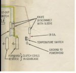
Reverse is blue, forward is green. Only one wire can have voltage on it at a time. Voltage on both wires at the same time will break things. No voltage on either wire is neutral.
 

Attachments

  • ShiftCoils.JPG
    ShiftCoils.JPG
    14.1 KB · Views: 0

Daviet

Fleet Admiral
Joined
Sep 24, 2008
Messages
8,958
Re: 63 johnson 40hp shifting diagram

I stand corrected, thank you. The way my memory works I feel pretty good about just getting the correct colors for the wires.
 

Eskort

Cadet
Joined
Mar 24, 2009
Messages
23
Re: 63 johnson 40hp shifting diagram

Ok, thanks for the info, I just went out and checked, i have voltage going to each green in forward and blue in reverse so I know the wiring is ok from the controls. From the diagram, the solenoids are grounded to the housing, resistance check from the blue cracked wire to the case shows me 7.8 ohms, and from the green to ground shows 1.8 ohms. Is this saying it is a bad solenoid or is it a whole assembly? I have never worked on this type of motor but am very knowledgeable when it comes to this kind of thing. I guess I need to remove the prop and dig deeper into the lower unit correct? Also, my buddies dad has 3 of these motors in his garage, I have been doing some wiring on a bush buggy for him and he owes me, lol, would it be better to change the whole lower unit or just the no good parts inside?
 

tx1961whaler

Vice Admiral
Joined
May 31, 2008
Messages
5,197
Re: 63 johnson 40hp shifting diagram

Always better to change the whole unit.
Those electric shift lower units need a special Type C gear oil for them to work properly.
 

Eskort

Cadet
Joined
Mar 24, 2009
Messages
23
Re: 63 johnson 40hp shifting diagram

Ok thanks, I am heading to my buddies tonight and hopefully pick up a good lower unit. Thanks, I will post what happens.
 

Eskort

Cadet
Joined
Mar 24, 2009
Messages
23
Re: 63 johnson 40hp shifting diagram

Ok, so my buddies dad said "yeah bring it out i have a lower unit for you". So i did. I came home with a complete 65 40hp, right from the key all the way back to the prop. Everything. Will the lower unit from the 65 fit my 63? If not i will have to change points and all that jazz but the motor is good, so either way im alright, but I know for a fact my motor runs like a top, so if possible, would like to keep it on there, also its the original motor that came with the boat and trailer. The model number for the one he gave me is RKL-27A
 

Eskort

Cadet
Joined
Mar 24, 2009
Messages
23
Re: 63 johnson 40hp shifting diagram

I went to the shop tonight and started working on the motor. Discovered that my motor is a short shaft and the one i got is a long shaft. Once i tore it apart, realized the only difference is the extension housing, the length of the drive shaft and the length of the wires for the shifting. Changed out the drive shaft with the original out of my motor, put my water pump in as the other was no good, but i didnt fire it up yet because i am draining the bottom end over night as a small amount of water came out. I will pick up some electronic shift oil tomorrow and see what happens. The motor i picked up also had a generator on it which mine was missing, installed that, put the hood off the 65 on mine as it is in better shape, polished it and it now looks brand new, a little degreaser on the rest of it and you will never know the age. Pleased so far with how things are going with this motor. One question though, the 40hp is on a 14 foot fiberglass, is it worth me putting the hydrofoil on it? The old bottom end had one but only because the cavitation plate was broken off. Im thinking of putting it on the new bottom end, whats your thoughts on that?
 

lindy46

Captain
Joined
Nov 27, 2008
Messages
3,886
Re: 63 johnson 40hp shifting diagram

Not sure why you'd need a hydrofoil. You said water came out when you drained the lower unit. That means there is a seal leaking somewhere. I'd sure be checking into that before putting it back together. Water will make short work of an electric shift lower unit.
 
Top