70's Lightning Energizer Ignition & tachs

pman7

Petty Officer 2nd Class
Joined
Nov 29, 2006
Messages
129
I've got a 71 Merc 500 with the Lightning Energizer Ignition on which I'd like to install a tach. After reading the Merc Service Manual and various other writings on this process I've become a bit gun shy. Most manuals seem to list the LEI system as an exception to most tach installation instructions. What is so unique about the LEI?

My Merc Manual is obviously old and recommends a specific tach along with a specific module (P/N 52552A3) to possibly protect the tach? Why does the tach need protection on the LEI system and not on others?

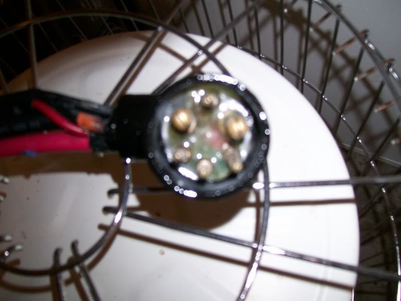
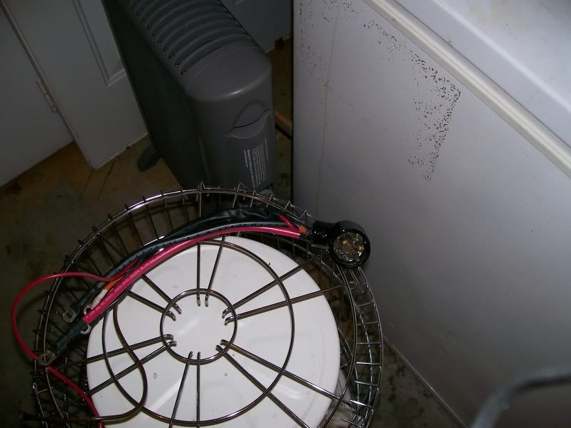
To get to the meat, I've purchased a Merc Tach (P/N 79-825348A1) to which I will attach a picture of it's back. From my understanding I should attach my 12V DC power line to the "IGN" post, connect a ground wire to the "GND" post and connect either wire coming out from under the flywheel (alternater wire) to the "SEND" post. I should also have the tach set to 6P for what I believe is my 12 pole alternater.

Will my new tach be safe if I do this? Is it possible to do any damage to my motor's electronics by doing this? I'm under the impression that with this tach I will not need the extra protector module, is this true?

I'll probably have a few more questions about methods to accomplish this but as for now, am I in the ball park?

2zt94lf.jpg
 

Attachments

  • Tach.JPG
    49 bytes · Views: 1
  • Tach.JPG
    49 bytes · Views: 1

erniex

Petty Officer 3rd Class
Joined
May 26, 2004
Messages
93
Re: 70's Lightning Energizer Ignition & tachs

Originally on my 73 Merc850, it said to use a Mercury tach only and it attached to the switchbox. This may be what the older service manual is refering to. I now use a generic marine tach connected and set as you described and it works fine. The send wire just attaches to one of the post on the rectifier connected to the stator. I don't think you should have a problem.

Ernie
 

pman7

Petty Officer 2nd Class
Joined
Nov 29, 2006
Messages
129
Re: 70's Lightning Energizer Ignition & tachs

Thanks Ernie.

My next question is how should I route the stator/rectifier post connection wire up to the tach?

On the MerCruiser controls there is a 3 blade connector plugin. Within that plugin is a white wire that goes to the 12v and a black wire that goes to ground. There also is a brown wire that combines with a salmon color wire when it passes through harness connector and then goes to the switch box you referred to.

Can I just detach that salmon/brown wire from the switch box and reattach it to the stator/rectifier post? This way I could just hook into the plugin on the MerCruiser control box plugin. Otherwise I'd have to run a wire out of my cowling back up to the tach.

How did you get your stator/rectifier wire up to your tach?
 

pman7

Petty Officer 2nd Class
Joined
Nov 29, 2006
Messages
129
Re: 70's Lightning Energizer Ignition & tachs

Rick: From a discussion in another thread I think that Teleflex drawing has the "Ign" post and the "Send" post backwards.

The paperwork that accompanied my Mercury tach says the "Ign" post should hook up to 14v connection (see the attached sketch in my first post). My paperwork says the "Send" post should hook up to the "Sender" which I would assume means the alternator or stator. If you'll notice on the Teleflex .pdf file, their connections are reversed to what my Mercury directions say.


But otherwise you're saying I should just run a separate wire. Where would you suggest this wire come out of the cowling? Do you attach it to anything (cables, other wires, etc. ) for support?

I was hoping to just switch the salmon/brown wire from the switchbox to rectifier input post to avoid extra wires coming out of my cowling.

Thanks for the answer Rick.
 

fishfinger

Recruit
Joined
Dec 6, 2006
Messages
4
Re: 70's Lightning Energizer Ignition & tachs

[whisper uid=87361]

could you perhaps help me with my 9.9 mariner post?
[/whisper]
 

ricksrster

Commander
Joined
Jun 19, 2005
Messages
2,022
Re: 70's Lightning Energizer Ignition & tachs

It is true. The Teleflex drawing is reversed. Send goes to yellow wire of rectifier. i would run it through an available opening in the cowl. You can wire tie it along with your harness to keep things looking neat ad out of the way. The 14v is from your ign. switch on position. You can use the white wire on the tach connector from the control box. The black wire is a ground. the light can connect to your other instrument lights or your navigation lights. According to the wiring diagram I have for your motor the brown tach wire on the control box connector doesn't connect to the internal wiring harness at the motor. Not all the pins and wires on the harnesses are used on every model. That is why a new wire should be run from the rectifier.
 

pman7

Petty Officer 2nd Class
Joined
Nov 29, 2006
Messages
129
Re: 70's Lightning Energizer Ignition & tachs

Rick:
Thanks again for your help. Your explanation of the function of the salmon wire finally triggered my realizing quite a bit more about my motor. I actually was not aware of the uniqueness of the Lighting Energizer Ignition system nor what made it different than most other ignition systems. It was just a cool name to me.

The difference being that this system has two electricity producing entities. The Ignition Driver produces the charge for the spark plugs and the separate alternator produces the charge for the battery and therefore the starter. The two share the same ground but are two different systems. I know this is probably a pretty simple concept for you but it was almost a revelation to me.

You essentially forced me to realize the only connection between the two systems was that salmon wire and the only function of that salmon wire was to ground out (kill) the ignition and to carry an ignition signal to the old style of tach that Mercury had suggested for use.

So now I believe the only possible way to get the alternator signal to my tach is to run a new wire, like your said, the entire way from the rectifier input to my tach or (correct me if I'm wrong or if this is impossible) to unhook the jump wire that connects the brown wire to the salmon wire circuit and connect that to the rectifier input.

This second option that I'm suggesting is posed as sort of a question to you. I'm merely going from the wiring diagram and not the real world. If I can get on the inside of that harness connector piece or at least find out if that jumper wire is accessible (from the diagram it looks like that jumper wire might be just inside and behind the female part of the harness connector piece that's on the motor).

I'll probably end up running the wire the whole distance but it would sure be cool if I can rewire that harness and get the 3-prong tach connector on the Mercontrol rewired for today's tachometers. :)

Thanks again for the help.
 

ricksrster

Commander
Joined
Jun 19, 2005
Messages
2,022
Re: 70's Lightning Energizer Ignition & tachs

Looking at the diagram: On the internal harness connector at pins E and G looks like the jumper you were talking about. If you could remove the jumper and run a wire from G to the rectifier it should work.
 

TriadSteeler

Petty Officer 1st Class
Joined
Oct 26, 2006
Messages
237
Re: 70's Lightning Energizer Ignition & tachs

I need to do exactly the same thing on a 74 Merc 500.

I have two salmon wires coming out of the internal which are fused into a single wire that lead to the switch box. (I don't know if this is Mercury or previous owner enhancement) From the diagram, I'm assuming that E (Harness) is the salmon wire coming from the E (ign switch) and G (harness) is the brown coming from the Tach Pigtail.

I have an extra external harness that is completely shot so I'm going to dismantle it and see what exactly connects to where within the plug. I'll let you know what I find.

If this would work, where can you find the male pigtail to make the connection? Can you buy that or would you have to find an old Merc Tach Harness?
 

pman7

Petty Officer 2nd Class
Joined
Nov 29, 2006
Messages
129
Re: 70's Lightning Energizer Ignition & tachs

Rick, is that the exact 3prong plug that will fit into the tach plugin on the control box?

I saw that Merc OEM harness sell on ebay a week or so ago for 33.50 plus 10 for shipping.

I found 2 places to order it for about 29 plus shipping. I belive the Merc part # is 84-46239A1.


Bob Grubb
Grubb's Marine Division
East Coast Marine Service
3363 West Ridge Pike
Pottstown, PA 19464
Phone: 610-495-7774
FAX: 610-495-6868
grubbs@oldmercs.com
We do have this harness #84-46239A1 for 29.55 plus 8.95 shipping and handling.


and

Twin City Outboard <tcoutboard@tcoutboard.com>
have one new for 29.33.
I think shipping will run about 11.00
Please call to order parts at 952.496.1951


Rick, if that one you listed is the exact 3 prong harness, your's is obviously the better deal.
 

ricksrster

Commander
Joined
Jun 19, 2005
Messages
2,022
Re: 70's Lightning Energizer Ignition & tachs

I looked up the part number for the one listed on iboats, IH15105, on the Teleflex web site. The one on iboats is a five wire plug.
 

TriadSteeler

Petty Officer 1st Class
Joined
Oct 26, 2006
Messages
237
Re: 70's Lightning Energizer Ignition & tachs

Here's the deal with the External Harness.

The E is the salmon wire going in and an orange coming out the other side on the internal. The G is the brown wire coming in and an another orange coming out of the internal.

The two oranges are fused under the cowl. My plan is to remove the Y connector and splice a brown wire to the orange wire that is in the G position and run it to the rectifier.

Here are some pictures:


Cross-Section of the External Wiring Harness
101_0061.jpg


Orange-Orange Splice from the Internal Harness
101_0063.jpg
 

pman7

Petty Officer 2nd Class
Joined
Nov 29, 2006
Messages
129
Re: 70's Lightning Energizer Ignition & tachs

TriadSteeler, thanks a million for taking the time to do that. I haven't yet completed mine and that certainly shows the plan is viable. I'll just figure out a way to determine which orange wire to cut away from the T. But I guess it won't be a big deal if I cut the wrong one and have to solder it back together.
 

pman7

Petty Officer 2nd Class
Joined
Nov 29, 2006
Messages
129
Re: 70's Lightning Energizer Ignition & tachs

Once you have the internal wiring harness out could someone give me some tips on rebuilding it?

Is it possible to cut into the main body of sheath and get at where the wires are hooked to the pins? Would it be just a matter of soldering new wires to the pins?
 

TriadSteeler

Petty Officer 1st Class
Joined
Oct 26, 2006
Messages
237
Re: 70's Lightning Energizer Ignition & tachs

If the internal is set up like the external, It would be nearly impossible to rebuild it. The insulators on those wires are fused to the rubber. look at my photo. I literally had to tear the thing in half. The insulators came off the wires because they were stuck so hard to the harness. If you have the hands of a surgeon you may be able to successfully split the harness on the seam and dig out each wire and glue it back together, but personally, I wouldn't attempt it.

You would be better off constructing your own harness and putting a gromet in the hole in the cowl, than to mess with your existing.

Your best bet is ebay. I got a whole new external with the control and the cables for $50. I now have the pick of the best ignition switch, choke button, and neutral start switch as well.

You can probably get an internal even cheaper via ebay. A new one is only $87.
 

TriadSteeler

Petty Officer 1st Class
Joined
Oct 26, 2006
Messages
237
Re: 70's Lightning Energizer Ignition & tachs

pman,

As it turns out my internal was shot as well. I got to thinking about your comment as to rebuilding it.

I started by taking a razor blade and splitting the harness right down the seam and cut it into two pieces. I was able to extract the wires and I heated the pins and extracted the wires from the pins.

I then bought new wires and soldered them into the pins and began the task of trying to reconstruct the harness.

I attempted to hollow out enough of the harness plug to get the wires re-run so that I could glue it back together. This proved to be an impossible task to run all the wires and get them aligned in the previous pin holes in a configuration that would allow me to put it back together.

Then an idea struck me. Why use this old plug? Make one of your own out of a piece of schedule 40 PVC.

Off to Lowe's I went. Instead of a piece of S40 PVC, I bought a 1-1/4" to 3/4" PVC Elbow. It was exactly the same depth as the original harness plug.

Then it was the same OD as the harness plug. The only issue was that the external plug wouldn't quite fit inside. (No problem, the grinder would take care of that)

So, for the whopping amount of 67 cents for the elbow, 8 dollars for two double-barrel tubes of LOCTITE epoxy, and 14.00 worth of marine grade wire, I set out on the task of building a new internal harness.

Step 1. Drill a hole into the rear of the elbow (The surface opposite the big hole). Use a dremel to "rough up" the inner surfaces of the elbow and hone out the big end until the EXTERNAL harness fits fully and snugly.

Step 2. Thread the wires into the big end of the elbow and out and up thru the smaller end.

Step 3. Liberally coat the EXTERNAL harness plug and the INTERNAL harness pins with white lithium grease (I had an old extra EXTERNAL [pictured above]) Then insert the pins (make sure they are good and tight) into the EXTERNAL and plug it into the new harness. (This will keep the pins in exact place they need to be)

Step 4. Fill the new plug with the double barrel tube of epoxy from the drilled hole in the back. (The LOCTITE brand works great because it has a long nozzle that mixes the two parts together. Makes very little mess)
You will need two or three of these tubes. I also squirted the epoxy down the little hole where the wires come out.

Step 5. Remove the external plug. Rough up the outer surfaces, prime and paint.

Voila, a new internal harness for about 20 dollars. Not too shabby.

Boat009.jpg


Boat011.jpg


Boat006.jpg
 
Top