KEYCHS1720
Cadet
- Joined
- Dec 3, 2020
- Messages
- 10
Motor: 97, 75hp,2st, 3 cyl, Mercury Serial 0D283222.
Remote Control: Mercury Remote Control 88688A26 - good condition
16' Shift Cable: Removed from boat, I believe to be original, smooth, appears to be in great shape.
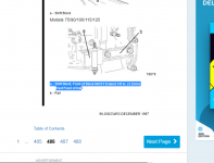
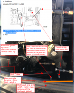
After performing an oil change, impeller change and bearing carrier seals I have found myself in a difficult decision with my lower unit and its shifting abilities. I'm able to locate F,N,R while spinning the shift shaft on the LU CCW. However, despite having the LU and remote control in neutral when I reassemble the motor, I'm unable to shift into forward from neutral at the remote control. I have adjusted the shift cable in everyway, I believe my problem lies with the timing/location of the shift-slide in relation to the shift lever/upper shift shaft and how it couples with the lower unit's shift shaft. I believe this is to be this issue because the shift lever disconnected from the shift block due to a loose bolt during this ongoing process. I've found a picture in the service manual , attached and link below.
Can anyone explain the significance of having the shift block pulled all the way to the front a 1/8 (3.2mm) past the front of the shift rail? I'll also take any advice anyone else has to offer!

 www.manualslib.com

Remote Control: Mercury Remote Control 88688A26 - good condition
16' Shift Cable: Removed from boat, I believe to be original, smooth, appears to be in great shape.
After performing an oil change, impeller change and bearing carrier seals I have found myself in a difficult decision with my lower unit and its shifting abilities. I'm able to locate F,N,R while spinning the shift shaft on the LU CCW. However, despite having the LU and remote control in neutral when I reassemble the motor, I'm unable to shift into forward from neutral at the remote control. I have adjusted the shift cable in everyway, I believe my problem lies with the timing/location of the shift-slide in relation to the shift lever/upper shift shaft and how it couples with the lower unit's shift shaft. I believe this is to be this issue because the shift lever disconnected from the shift block due to a loose bolt during this ongoing process. I've found a picture in the service manual , attached and link below.
Can anyone explain the significance of having the shift block pulled all the way to the front a 1/8 (3.2mm) past the front of the shift rail? I'll also take any advice anyone else has to offer!

Gearcase Installation - Mercury 75 Service Manual [Page 486]
Mercury 75 Manual Online: Gearcase Installation. Disconnect (and isolate) spark plug leads from spark plugs before installing gear housing onto drive shaft housing. Failure to follow this warn- ing could result in accidental engine starting and possible injury. a c 1. Position outboard...


