98' Mercruiser 3.0L Drive train interruption. bent push rods etc?

Tycer

Petty Officer 2nd Class
Joined
Jun 20, 2019
Messages
118
New Head gasket and manifold gasket will be here tomorrow. Any chance some of the new lifters could be damaged? rockers are pumping and compressing the new springs.

You can compress the #2 lifters to see if one is frozen. You can swap #2’s lifters with a different cyl. and recheck compression. The new lifters haven’t yet mated with the cam enough to matter. Have you had your spring pressure tested? Are all the rocker studs in line? Are they all the same height? I’m trying to work with the compression without pushrod scenario here.
 

Tycer

Petty Officer 2nd Class
Joined
Jun 20, 2019
Messages
118
Don’t need bolts. Do chase bolt holes with tap. Are your lifter bores galled? Consider taking the head in for a proper 3 angle valve job and spring check.
 

Scott Danforth

Grumpy Vintage Moderator still playing with boats
Staff member
Joined
Jul 23, 2011
Messages
50,268
Your gauge is suspect. Any value over 150 psi is either a bad gauge, or water/oil in the cylinder.

Use simple logic. A 10:1 compression ratio would be 147 psi (atmospheric pressure is 1 bar or 14.7 psi)
In fact mercruuser used to publish cranking compression at 150 psi

So at 170 psi, either your gauge is off or you have something in the combustion chamber taking up space
 

T4Frog

Seaman Apprentice
Joined
Sep 15, 2019
Messages
30
Thanks for the updates. Great info shared by all!

Scott, I know the gauge was older, and is stuck at 20 Psi for a start point. I just concluded it went to 190 so take away 20 Psi and call it good. I'll get another and post the results. Plan on running her this weekend on the water if all is as simple as it seems.

Tycer, last I checked, in July prior tp putting in the new lifters, the lifter bores were clean and sharp edged.I'll try and see if I can compress the #2 lifters and see if one is sticking. I ran it without the rockers on and got a 170 psi in cyl. 2 so concluded it was the valve sticking intermittently. The springs are brand new spring over damper as well. The 3 angle valve job might be in order should this weekend repair and test not fly. I will say, most all of the parts are Elgin, a brand that I was told was good. Looking at the Elgin valves in the head from the locks, to the face that meets the rocker seat, I am seeing that not every valve stem above the lock is the same length. I would expect better tolerances when manufacturing something this critical. I understand that the valve lash is adjustable to compensate, but still. Yes studs are in line and same height. That was one of the earlier things I suspected. I will chase the head bolt bores with a tap to clean out the threads.

Rick, unfortunately, I've got another set of Mahle/Mercruiser gaskets coming tomorrow via Amazon next day delivery. "Gotta try it twice to know for sure you don't like it!" I use Summit Racing a bit and wished I had known to look their way for boating. FelPro had some less than quality products back in the day. I'm glad to hear they stepped it up. I had no idea the GM and Mercruiser blocks and heads were so close! I figured they were bored differently and certainly with higher end performance heads. Another good bit of info. Today while looking for head gaskets, I found out the 3.0L 181ci is widely used in fork lifts and other industrial equipment from companies like Hyster and Caterpillar. Head gaskets were selling out of Cali for $8.50 a piece on Ebay. I didn't want to chance it or to wait a week or so for shipping. Thanks for reviewing the pictures and clarifying the head gasket being normal.

Very much hoping I'll post some success pictures here real soon.
I am heavily leaning toward a blown/gapped head gasket being cause for low/no compression in cylinder 2 and bubbling water lines with the leak down test. Calling it a timing related result with the high rpm prop fowling.
The plan is by Monday I will post the progress and findings here as an update. Again, thanks for going down the unusual roads for possible cause and effect problems.

Best,
Ralph
 

T4Frog

Seaman Apprentice
Joined
Sep 15, 2019
Messages
30
This eve, having replaced cylinder 3 I/E valves and the damaged Intake rocker yesterday, I decided to test compression with a new compression tester as recommended by Scott D. Today was a day of learning, and not all was positive. For starters, I woke up sick as heck and did some research. Apparently the blood donations I've been making to the local mosquito population came with a cost. They give West Nile Virus, and EEE in return.

I cleaned up the head and block yesterday and ran a tap down the head bolt holes as Tycer advised. This eve, I did a planned trial compression test, placed the head on using the cleaned up bolts without thread sealant, used the old but intact head gasket, approximated the valve adjustment and ran through the compression test with more true but not all positive results.

Cyl 1: 148 PSI
Cyl 2: 0 PSI
Cyl 3: 126 PSI
Cyl 4: 115 PSI

I found that 2 rockers (One in each of my troubled cylinders) where dry and have not been getting oil. Now I'm looking towards the new lifters, which I had soaked in mineral spirits before install not pressurizing with oil and not oiling the top end. Also thinking cylinder 2 valves are burnt and sticking, and need replacing. Here's what also leads me that way. While watching the rockers in motion, cylinder 2 exhaust valve was getting a double tap instead of an open and closed down then up motion. I kind of worried the cam lobe was damaged initially, but now I'm thinking the lifter isn't holding pressure.

It's time tp pull off the lifter/push rod cover (which I gasket sealed the heck out of to seal up) and pull the lifters out and inspect. Following a re-test, I'll pull the head and change out Cyl. 2 valves, maybe cyl. 4 valves and all the rockers also.

Any tips for going about the lifter check? Planning on opening them and checking for obstructions and any damage, misshapen tunnels in the block, etc.
 

Attachments

  • photo321307.jpg
    photo321307.jpg
    394.2 KB · Views: 0
  • photo321308.jpg
    photo321308.jpg
    535.9 KB · Views: 0
  • photo321309.jpg
    photo321309.jpg
    379.4 KB · Views: 0
  • photo321310.jpg
    photo321310.jpg
    540.1 KB · Views: 0
  • photo321311.jpg
    photo321311.jpg
    388.4 KB · Views: 0
  • photo321312.jpg
    photo321312.jpg
    359.3 KB · Views: 0
  • photo321313.jpg
    photo321313.jpg
    568.9 KB · Views: 0

Tycer

Petty Officer 2nd Class
Joined
Jun 20, 2019
Messages
118
So if you didn’t pull the block’s oil galley plugs and chase them there could be crud in the lifters. Also driving the oil pump with a drill is a good practice before firing a new motor. You’ll see oil bathing every rocker. An old modified distributor works well for this.
Regarding checking the lifters, just use a push rod and compress them and see if they fill up and expel like a little pump.
Again, I recommend having the heads done at a shop. I’ve done them myself with access to the proper tools and there’s an art to it. I never learned that art so I pay the pro.
Good luck and thanks for keeping us in the loop!
 

T4Frog

Seaman Apprentice
Joined
Sep 15, 2019
Messages
30
Tycer,

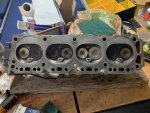
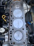
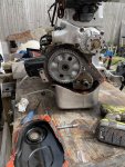
I did pressure wash the heck out of the block following acid baths and scrubbing. Then the machine shop tanked it so my conclusion, the block was clean. From there all new parts went in by me, Ebay Elgin brand 3.0 rebuild packages. I did my best for rebuild "in the house, bagged nightly engine assembly.

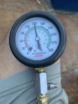
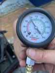
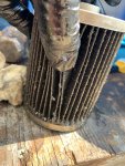
So here we are, cylinder 2 at zero compression, with a dry rocker.
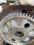
Cylinder 3 at 126 psi with a dry rocker, new lapped Elgin valves, New Elgin rods, and a new Elgin rocker and nut assembly, and still the rocker is trying to walk off the valve stem seat.

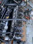
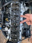
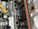
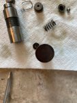
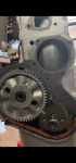
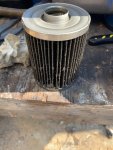
I pulled the pushrod access cover off, pulled the two offending pushrods and here's what I found;

Cylinder 3 was first. Dry although the lifter had a small amount of oil in the cup, I had a time compressing it and only got it to go down a small amount with oil expelling out the side of it. Calling it partially frozen or sticking.

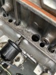
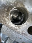
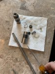
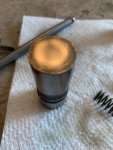
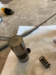
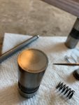
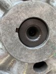
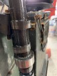
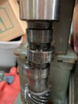
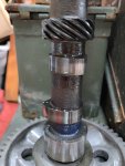
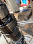
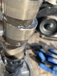
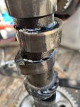
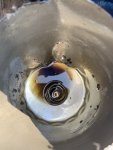
Cylinder 2 lifter. The cup was full of oil, yet none was getting up the push rod! I could not compress the lifter with as much pressure as I could put on it with the push rod and other methods. I'm sure you're realizing the answer. Even I was drawing conclusions, with your guidance, at this point. I pulled the lifter...... 1/2 way, just above the oil pick up groove, before it refused to come out. Vice grips and a little twisting and she came up and out. The Elgin lifters do not have the hardened faces like the factory ones I pulled did. Wish they did. My old ones looked great, but from my understanding, you should never mix old and new parts.. New Elgin cam shaft also. Lobe looked ok through the lifter tunnel.

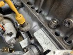
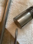
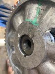
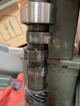
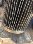
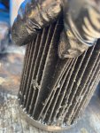
The seat of the lifter that rides on the cam had a slight amount of mushrooming. I felt the rough edge when I got it out and then when I took it in for inspection, as pictures indicate, I saw and felt the problem that I could not compress the lifter with. I found some small metal fragments inside the lifter between the plunger and side wall, and never was able to depress it. My guesstimating, this was most likely causing the C2 zero compression. I also found the small New lifters are a whopping $3.50 a piece available at Autozone 2 miles away. I really want to find new, or use my old hardened face lifters. If I do, I'll likely replace them all.

Now my paranoia has got me wondering about the other lifters that are oiling, and the metal lifter fragments I likely knocked off while pulling the lifter out. Some lifters are oiling very well (Cyl. 1) and others off and on moderately well. I will test cycle many times before closing it up, putting the valve cover on and test running on the water for some level of safety. The oil is pristine BTW.

Once again Tycer, Thanks for the lifter advice and thank you to all forum members who gave their input. Hopefully, the bottom of this problem has been found, and hopefully this detailed forum post helps others so they are able to avoid some of the suffering. I'll update when she's running, and likely I'll watch the lifters with regular valve cover removal checks for a while.

Best, Ralph
 

Attachments

  • photo321326.jpg
    photo321326.jpg
    520.7 KB · Views: 0
  • photo321327.jpg
    photo321327.jpg
    551.5 KB · Views: 0
  • photo321328.jpg
    photo321328.jpg
    385 KB · Views: 0
  • photo321329.jpg
    photo321329.jpg
    441.4 KB · Views: 0
  • photo321330.jpg
    photo321330.jpg
    479.3 KB · Views: 0
  • photo321331.jpg
    photo321331.jpg
    345.9 KB · Views: 0
  • photo321332.jpg
    photo321332.jpg
    509.3 KB · Views: 0
  • photo321333.jpg
    photo321333.jpg
    314.4 KB · Views: 0
  • photo321334.jpg
    photo321334.jpg
    262.2 KB · Views: 0
  • photo321335.jpg
    photo321335.jpg
    232.8 KB · Views: 0
  • photo321336.jpg
    photo321336.jpg
    312 KB · Views: 0
Last edited:

T4Frog

Seaman Apprentice
Joined
Sep 15, 2019
Messages
30
New lifters in and they oil the top end well. Unfortunately, the problem is deeper than new lifters, which don't all oil to the rockers at the same level. Some soak the rockers with great pressure while cranking.. . Some just cut it. Here's my speculation as to why. They are full of metal fragments from the cam shaft lobe in cylinder 2. It is chipped off or rounded as intake lifter 2 goes up a little, dips slightly downed, then up a little while peaking. I've reached the point of pulling the engine and saving what I can. Cleaning it out, replacing the cam and what ever else got damaged before the cylinder walls get scratched. Hopefully, the oil filter gets first dibs on the metal fragments before oiling the piston rings. Not at all what I expected when peeling back the skin of an onion I just rebuilt from the core.
 

Rick Stephens

Admiral
Joined
Aug 13, 2013
Messages
6,118
Wow Ralph. What a sucky story. I wondered... early in the story, if you were getting oil gallery flow like you should. Is it possible some of the gallery is plugged?
 

T4Frog

Seaman Apprentice
Joined
Sep 15, 2019
Messages
30
Rick, Good point. With the internally rusted state of the block before hand, it's definitely possible and something I'll have a look at. I'm not sure how the oil passages route, but I'll make it a point to check upon disassembly. I figured since it was tanked by the shop, on top of what I did to clean it up, all would e good. Not something I made a point to check.
 

T4Frog

Seaman Apprentice
Joined
Sep 15, 2019
Messages
30
I found the bottom of the money pit for this engine... "I believe" ... and I'm calling it a good find. I pulled the engine, set it on a bench and began disassembly, focusing on the camshaft removal to see what I had. 4 hours after starting, I found the cause for my chewed lifter. Initially, after inspecting the cam, which looked damn good, (just like a new cam should) compared to the way the lifter was behaving for cylinder 2, I felt it must be a stuck valve. In fact it is not. Looking over the cam, pictures provided below, all lobes looked very nice, just as they should with a little polishing on the lobes. One lobe had a gouge along the outer edge, which made no sense, since it was the new fuel pump lobe which only rides in the middle of that lobe. Then I realized what happened, just not exactly why.
Here's what happened. My cam walked in and the valve lifter fell into the valley between the fuel pump lope and it's lifter lobe, which explains why it's cam face was chewed on the edges and it lifted funny and not high enough to open the valve. I full throttled it for about 10 -15 seconds without good matching RPM outcomes when the RPM's began to drop after the crab pot line began fouling the prop.

The cam looks great as pictures will show, less a race and some burs on the outer edge of the fuel pump lobe.

The cam is recessed back into the block as the cam gear picture shows. It was flush when I pressed the old but still sharp clean looking cam gear onto the new cam. (I'll post pictures before and after).

My question; Why did my cam walk in?

Again, I'm not a mechanic or engineer. I am using my deductive reasoning and coming up with possible causes, but I need to know the cause before reassembly. My thought process is this, neat to more involved.

Cause possibility #1. The higher 3400 rpm high torque fight I had with the crab pot itself while the engine was just being broken in, pulled the cam back slightly out of the cam gear (key is in place as it should be and gears are correctly aligned) causing the intake valve lifter to drop into the valley, which started the failure problem.

Cause possibility #2. When replacing a cam, you should also replace a new cam gear which should likely only be pressed on and off once or the aluminum gear will not mate to the keyed new cam quite as tightly as needed.

Cause Possibility #3. when replacing the rear cam freeze plug after installing new cam bearings, it must be pressed all the way till it contacts the rear cam bearing to be a stop for the camshaft and prevent walk. I pressed it in to where the old one was from the outside view, about 1/8" into the block. Possibly it was not s deep a plug as the factory and did not make contact with the back of the cam, if it should.

Cause possibility #4. perhaps with me getting creative, not having a cam bearing tool and possibly putting the wrong cam bearing in the # 3 back bearing spot, (I went through 2 sets to get it right with a rear that was a little too tight before I lightly shaved it to work). I heard the bearings are different sizes and possibly the rear lead babbet bearing is conical and now is not and does not thrust the cam forward as it was intended to.

If this were the case, 1 and 2 are correct, Bearings do not come marked placement wise or front/back edge, 3 in a box. All oiler holes are correctly lined and they look good less a slight surface rub removing the cam today. Gotta take out the fuel pump first.

Question 2. Drained the oil through a doubled layered nylon cheese cloth type of material (photo below). No fragments, but the grey indicates the break in of the new parts I believe? Will the oil feel ever so slightly gritty between fingertips?

My plan. 1. Get the answer from those with wisdom. 2. clean and reinstall the cam. Possibly with a new cam gear, and drop an engine oil pan magnet into the oil pan. Change the rear bearing and freeze plug if that effects things.

Thanks for the guidance. Detailed photos below.
 

Attachments

  • photo321475.jpg
    photo321475.jpg
    261.9 KB · Views: 0
  • photo321476.jpg
    photo321476.jpg
    624.4 KB · Views: 0
  • photo321477.jpg
    photo321477.jpg
    500.2 KB · Views: 0
  • photo321478.jpg
    photo321478.jpg
    518.8 KB · Views: 0
  • photo321479.jpg
    photo321479.jpg
    737.5 KB · Views: 0

T4Frog

Seaman Apprentice
Joined
Sep 15, 2019
Messages
30
[No message]
 

Attachments

  • photo321482.png
    photo321482.png
    1.3 MB · Views: 0
  • photo321483.jpg
    photo321483.jpg
    415.6 KB · Views: 0

T4Frog

Seaman Apprentice
Joined
Sep 15, 2019
Messages
30
Cam lobes wearing nicely on new cam for cyl.4, 3, 2 and 1. Shinny race with on edge of fuel pump lobe between cylinder 2 valve lobes.
 

Attachments

  • photo321480.jpg
    photo321480.jpg
    351.9 KB · Views: 0
  • photo321484.jpg
    photo321484.jpg
    345.2 KB · Views: 0
  • photo321485.jpg
    photo321485.jpg
    384 KB · Views: 0
  • photo321486.jpg
    photo321486.jpg
    381.8 KB · Views: 0
  • photo321487.jpg
    photo321487.jpg
    379.9 KB · Views: 0
Last edited:

T4Frog

Seaman Apprentice
Joined
Sep 15, 2019
Messages
30
Cam gear teeth with low to no wear, block front with cam gear removed, fuel pump lobe with race. All other lobes clean wear, no scorching, races or chipping.
 

Attachments

  • photo321487.jpg
    photo321487.jpg
    379.9 KB · Views: 0
  • photo321490.jpg
    photo321490.jpg
    389.4 KB · Views: 0
  • photo321492.jpg
    photo321492.jpg
    656.8 KB · Views: 0
  • photo321493.jpg
    photo321493.jpg
    305.1 KB · Views: 0
  • photo321494.jpg
    photo321494.jpg
    334 KB · Views: 0
  • photo321495.jpg
    photo321495.jpg
    341.1 KB · Views: 0
Last edited:

Rick Stephens

Admiral
Joined
Aug 13, 2013
Messages
6,118
Earlier, your shots down through lifter holes, seemed the cam didn't line up with the holes.

Way way too much metal in your cheesecloth. Cut your filter in half and see what's in it.

Rick
 

cobalt1999

Petty Officer 2nd Class
Joined
Apr 28, 2010
Messages
102
Looks like what your problem is that the camshaft gear is not pressed onto the camshaft properly.
The nose of the camshaft should be flushed with the face of the gear.
The retainer plate should be closer to the journal.
There should be a ring or step that the retainer sits over and the gear bottomed out against it.
 

T4Frog

Seaman Apprentice
Joined
Sep 15, 2019
Messages
30
Cobalt, the problem is that the cam pulled from the cam gear and recessed into the block. The retainer plate was in place and torqued, keeping the cam from moving forward out of the block. Here is a better/larger picture just prior to rebuild completion with the cam pressed flush with the gear face.

Rick, I'll use some hand sheers and cut the oil filter open today as to not create additional metal particles (Picture to be posted). Since you steered me that way, I understand what we're gonna find. What I don't understand is the end result, and why this happened? How to correct the cam pulling in issue? Not 100% sure, but believe I am going to have to do a complete tear down and clean out and possibly all new bearings or worse.
 

Attachments

  • photo321482.png
    photo321482.png
    1.3 MB · Views: 0

T4Frog

Seaman Apprentice
Joined
Sep 15, 2019
Messages
30
Rick, Thanks for steering me the route of the oil filter. I opened her up and was surprised what I found, and it helped me to recall a key factor related to my choice of overly generous use of assembly lube. Pictures below of the filter, filter cup, assembly lube I chose and it's color. The grey stained rag from yesterday had no glitter, no sparkle and in fact was black moly assembly lube with graphite. There is no sparkle in the oil filter either. A small amount of grit, likely from my opening the difficult oil filter and a lot of black moly clumps as pictured. No shiny glitter.
 

Attachments

  • photo321514.jpg
    photo321514.jpg
    566 KB · Views: 0
  • photo321515.jpg
    photo321515.jpg
    689.5 KB · Views: 0
  • photo321516.jpg
    photo321516.jpg
    753.1 KB · Views: 0
  • photo321517.jpg
    photo321517.jpg
    761 KB · Views: 0
Last edited:

T4Frog

Seaman Apprentice
Joined
Sep 15, 2019
Messages
30
Pleats look good less their graphite black color and goops of assembly grease. And for my next rebuild, red assembly lube will be used. Going to have a look at ALL of the lifter faces. Expecting only the one cyl. 2 problem lifter to be flawed. Will soak them all again, disassemble and clean. It's 94 and humid here in VA Beach today and so not a normal October day good for working on anything.

Recommendations from here? Especially related to the Cam movement?
 

Attachments

  • photo321518.jpg
    photo321518.jpg
    1 MB · Views: 0
  • photo321519.jpg
    photo321519.jpg
    1.4 MB · Views: 0

T4Frog

Seaman Apprentice
Joined
Sep 15, 2019
Messages
30
After a few different forum searches on pressing aluminum cam gear on and off I found some detailed info, including this from a more experienced forum member; "Never reuse a gear that has been pressed on already. It's painful to buy another gear. It's way more painful to tear the engine down again."

I also found some said although engine manuals don't mention heating the aluminum cam gear, most shops heat it from 300-400 degrees prior to install and some recommended freezing the camshaft overnight.

All of my lifter lobes less the one earlier pictured cyl. 2 lifter edge were flawless.
 
Top