Adding an isolator

wxkeep

Cadet
Joined
Apr 27, 2008
Messages
10
Have a mercruiser 3.7LX Alpha one on my 1990 Regal Sebring. Installed a new stereo to listen to while sitting in the cove and quickly realized my need for a second battery. =(

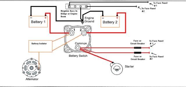
I've done a lot of research on how to hook everything up - I have two batteries, a switch, and an isolator. At first everything seemed fairly straight forward - connect the alternator to the isolator - the 1 and 2 posts of the isolator to the switch - those posts to the battery and the common of the switch back to the motor.

Seems fairly straight forward. HOWEVER - I crawl into my engine and I get confused. Currently I've got a red cable running straight from my cranking battery to the starter. From there - there is also an orange wire (that normally I would assume runs to the alternator) that runs to a voltage regulator. There is also a yel/red wire connected to the starter that runs to the slave solenoid, and another red wire that runs to a circuit breaker that runs a red/pur wire back to the voltage regulator.

Now, if I'm correct, I think I should take the orange wire to the isolator, and leave the yellow/red wire on the starter. ANother red wire should go from the starter off to the switch, but what do I do with that last red wire that runs to the circuit breaker and back to the voltage regulator???

Or is the voltage regulator a type of isolator and my isolator is not needed?

I've been reading everywhere - but can't seem to find out what to do. Any help that you guys could provide, would be greatly appreciated!!
 

zibzer

Petty Officer 2nd Class
Joined
Apr 28, 2007
Messages
114
Re: Adding an isolator

are you having problems with current draw while the motor is running or while stopped? .. and is this a manual or auto isolator?
 

wxkeep

Cadet
Joined
Apr 27, 2008
Messages
10
Re: Adding an isolator

Don't know that I have any problems, to be honest. Perhaps I just got sold on something I don't need...=( But I'm putting in an amp and new speakers into the boat and the guy at the shop suggested I get the isolator AND the switch. It's a 70amp isolator...little black box with three posts on it - don't know much more about it than that.

The way it was suggested to me is that the isolator will protect the alternator in case my amplifier tries to pull more power than the alternator can generate. I don't know how much my alternator generates OR how much amplifier pulls (although I could probably look up the second information relatively easy).

Does that help?
 

Don S

Honorary Moderator Emeritus
Joined
Aug 31, 2004
Messages
62,321
Re: Adding an isolator

For one thing, if your electrical system is the oem sysnem on that engine, it doesn't even have an alternator. You have a rotor/stator ouboard type charging system with a raw water cooled regulator. Unless you are planning on having a stereo system that creates tidal waves and boat rage from anyone within a mile of you, you probably don't NEED all that while the engine is running.
Having said that, if you plan on spending a lot of time at anchor listening to CD's and the normal things done on a boat, for long period of times without the engine running, then maybe you need an isolator. More so to have a fullly charged battery to start the engine than anything else.
The isolator DOES NOT protect an alternator in any way shape or form. All it does is allow the battery with the least amount of charge to be charged the most.

For more answers to your question, moving this thread to the Electrical, Electronics forum.
 

zibzer

Petty Officer 2nd Class
Joined
Apr 28, 2007
Messages
114
Re: Adding an isolator

I cant see the charging system not being able to keep up while running unless you have one helluva loud system. and as far as being parked and listening. it may be a good idea to have the isolator to keep a fresh battery for starting,.

since you have the thing anyway ill draw up a diagram to show how it should be wired... give me a little while
----
hey don. no disrespect intended, but what do you mean a "stator/rotor" charging system.. the stator is the outside of a motor/alternator... and the rotor is the inside rotating part of an alternator/motor... im not too sure i follow you. Though im more of an industrial electrical type person though so maybe theres something im missing.
 

Reel Poor

Vice Admiral
Joined
Jan 29, 2005
Messages
5,522
Re: Adding an isolator

Your engine did not originaly have an alternator. It's very likely an aftermarket alternator kit has been installed, if so maybe this will help.

DualBatteriesIsolator002.jpg
 

zibzer

Petty Officer 2nd Class
Joined
Apr 28, 2007
Messages
114
Re: Adding an isolator

This will work for you.. cheers!

isolator.gif


you also have the option of using a switch to dictate which battery you want all loads to run off of. which is how reel poors diagram is shown
 

wxkeep

Cadet
Joined
Apr 27, 2008
Messages
10
Re: Adding an isolator

You guys have been a TREMENDOUS help, but I have to admit, I'm still a little confused.

No, I don't forsee major problems when the engine is running. My concern is that my typical day includes skiing for 2-3 hours and then sitting in the cove listening to tunes for 4-5 hours (sometimes more on the holidays), and I don't want to go dead. My thought is - when I'm in the cove - flip the switch to battery 2 - so if I DO happen to kill the battery - I can switch back to 1 to start the motor and be on my way back to dock. While driving around - flip the switch to both so that I can make sure that the motor charges the batteries that need it.

Yes, looking at the manual - I do have an alternator rotor/ stator system. I don't think anything has ever been changed on the boat (it only has about 500 hrs on it)...

BUT - my question is this - there are (according to the manual) TWO wires that run from the stator to a voltage regulator. Out of that one wire runs straight to the starter and another runs into a circuit breaker and THEN into the starter.

As I look at the starter - there are 4 wires attached to its post:
The battery lead
the cabel running to the starter solenoid
and the two running to the voltage regulator/stator.

do BOTH of those wires need to go on the "alternator" post of my isolator? Or does one stay on the starter??

Thanks again for all your help! You guys are great!
 

Boatist

Rear Admiral
Joined
Apr 22, 2002
Messages
4,552
Re: Adding an isolator

I respect Don and hope he will come back but do disagree that the isolator with his statment that the isolator does not protect the Alternator or stator rotor. The isolator does protect the alternator or rotor stator. Since your charging system runs to the isolator then to the back of your switch for battery one and for battery 2. If someone turns the switch thru off with the motor running it will not blow the alternator or charging system as would normally happened. Both batteries are still connected to the charging system so if the switch is turned thru off the voltage will not rise any higher than normal. Without the isolator the voltage would go so high it would blow diodes is the alternator or voltage regular or diode block.

The diagram that Reel Poor sumited is very good but just to be clear the heavy red line from the common on the switdh and going down at a angle is connecting to the starter solenoid then to the starter thru the solenoid.

The red wire on your battery should not go to the starter. It should go as shown to post one on the switch and also have the isolator output 1. Also the voltage regulator input should also go to this post 1 on the back of the switch.

The heavy alternator or charging output should go to the common post on the isolator.

Battery 2 should go to post 2 on your switch. I would also wire a heavy wire to a fuse box and run all you stereo equipment off this fuse box. If you wire it this way You never need to change your switch unless battery one is dead and you want to start off battery 2. If wired this way with the switch set to postion one then the motor will start off of battery one. The alternator will charge both batteries thru the isolator. When you stop you do not need to change the switch as the stereo will run off of battery 2 and anything you connect to that fuse box. Wired this way you never need to turn the switch unless you want to start off of battery 2. If you turn the switch off with the motor running it will not hert the charging system. If turn the switch off the starter will not work but the stereo gear will still be connected to battery 2 so if left on can run battery 2 down.

Some will tell you not to wire this way but instead wire the fuse box for your stereo to the common post. This will also work but when have the switch in position one and stop for lunch or listening to the tunes the stereo will be running off of battery 1 so you would need to go back and turn the switch to postion 2 so it runs off of battery 2. Wired this way when you turn the switch to off the starter is off and the radio is off also. The disadvantage is you need to change the switch to start off of battery 1.
 

zibzer

Petty Officer 2nd Class
Joined
Apr 28, 2007
Messages
114
Re: Adding an isolator

only one of the wires from the regulator go to the isolator. yet im still a little confused, without being there or having wired your exact motor before im not too sure I can help much more.
 

wxkeep

Cadet
Joined
Apr 27, 2008
Messages
10
Re: Adding an isolator

Here is a scan of the manual showing the wiring diagram for my motor - maybe that will help?

I'm curious as to the orange and the SMALLER (at least as it is represented in the diagram) red wire. I think I leave the yellow/red wire right where it is.

Thanks!
 

Attachments

  • mini-scan.jpg
    mini-scan.jpg
    59.3 KB · Views: 0

zibzer

Petty Officer 2nd Class
Joined
Apr 28, 2007
Messages
114
Re: Adding an isolator

yes. certainly yellow/red stays put. does both the red (from regulator) and orange (from regulator) end up at the same starter terminal or are they seperate? its certainly a confusing setup. im trying to figure out why mercruiser thought it was necesary to run 2 wires to the starter from the regulator.

I definately agree the orange is the regulators output. what what does RED (RED/PURPLE) do.. thats a head scratcher.
 

wxkeep

Cadet
Joined
Apr 27, 2008
Messages
10
Re: Adding an isolator

Tell me about - hence why I came here looking for help. =)

yes - all of those wires are hooked up to the same post on the starter. That post has:

1) The large red running from the battery
2) The yellow/red runnign to the solenoid
3) the orange running to the voltage regulator
4) the red running to that circuit breaker thing
5) AND another hot lead that runs to, I believe, my trim motor.

Now, I just got off the phone with mercruiser (and the lady sounded like she was guessing a little bit - which makes me nervous) but she explained that the orange IS the alternator/stator output. That the yellow/red is for the starter soleoid and that the OTHER little red that goes to the circuit breaker and then off to the voltage regulator is a preventive measure - meant to blow the circuit before burning up the voltage regulator/or stator. (But isn't that what my isolator is for? and if so do I need both?)

She said that I should leave THAT wire, along with the yellow/red wire and the trim motor wire all on the starter. Run the orange wire to my isolator. run my isolator to my switch and batteries and then run a lead wire from the common post of the switch back to the starter.

It SEEMS to make sense - but I'm hoping to find just one more "confirmation" from someone before I do it. =)
 

zibzer

Petty Officer 2nd Class
Joined
Apr 28, 2007
Messages
114
Re: Adding an isolator

that sounds logical. Like i said before i did believe the orange was the output.

After reading her explanation it sounds to me that the red wire is running all the components on the engine, but the orange wire is for starting only. Thus if your running the engine and for whatever reason the orange wire falls off, or corrodes off, or gets cut up by something then the little wire is making certain the engine will still run and the sensors will all still work. Why they thought this was necessary is anyones guess... though copper was a lot cheaper in the early 90s :)

I would do exactly what she says and find out what happens. i highly doubt anything bad will happen :cool:

Make sure you wire the isolator like ReelPoor suggested (since you have a switch already) and bring the orange to the "Alternator" post on the isolator..

Good luck!
 

Boatist

Rear Admiral
Joined
Apr 22, 2002
Messages
4,552
Re: Adding an isolator

What the Lady told you looks exactly right to me.

The orange wire from the voltage regulator should be a heavy wire 10 or at least 12 guage and it should go to the Isolators common post.

From the isolator wire the output 1 to the battery 1 on the switch and output 2 to battery 2 on the switch. I would use the same size wire Orange if you can find it or Red. The battery cable from battery 1 also to switch post 1. Battery cable from battery 2 to the switch post 2.

Common post from the switch should be the same size wire as your battery cables and go to the Starter solenoid post that battery 1 is now connected to. Should be a red wire. Your starter solenoid is on the starter. The slave solenoid is run by the key switch and should be left as wired.
The circuit with the circuit breaker As the lady said should be left as is.

Isolator main function is to allow you to charge both batteries while isolating the batteries so if you have a bad battery it does not discharge the other battery. Your switch is to allow you to start off of either battery. You should never run the switch set to both as this would allow the weaker battery to discharge the stronger battery. Isolator will also protect the alternator from turning the switch thru off as the load of both batteries is felt by the alternator. You do not have an alternator but rather a rotator and stator. The voltage regulator is acually a rectifier, voltage regulator and has some form of saftey kill circuit to protect the rectifier and voltage regulator. Once again DON was right. An alternator would have a field winding and charge more at idle conditions. Your unit has magnets in the rotator to induce current in the stator.

You can still decide how to set up your switch as I mentioned in the last post.
If you wire the big amp and stereo to the common post then when you stop you should turn the switch to position 2 so you run down battery 2 and not your starting battery 1. Then before you start switch back to battery 1 to start off battery 1.

If you wire your amp and Stereo up to post 2 on the switch then when you stop you do not have to do anything. Stereo will run off battery 2 and you will still start off battery 1. Only thing to remember here is with the switch in the off postion battery 1 will be disconnected but the stereo will still be connected to battery 2. This is the way I would wire but I would also add a lighted switch for you stereo or a switch with a led to let you know the stereo still has power. If you remember to turn off the stereo do not need the switch and light. In my case without the light some day I would forget and end up with a run down battery 2 and damaged battery 2.
 

wxkeep

Cadet
Joined
Apr 27, 2008
Messages
10
Re: Adding an isolator

You guys have been great! I feel a lot more confident about how to wire this project up now, which makes me feel a WHOLE lot better.

LAST question (I promise) in the last post you mentioned I wouldn't want to run with the switch in the "both" position as the weaker battery would discharge the stronger battery. Is that a NEVER do it - or never do it without the motor running to keep them charged?

If the answer is NEVER do it - and I wire everything up to battery 2 and leave the switch to 1 - how would I ever charge the second battery? Not off the motor? But rather at home on a full scale charger?

Thanks again - I can't express enough how helpful you have all been!
 

zibzer

Petty Officer 2nd Class
Joined
Apr 28, 2007
Messages
114
Re: Adding an isolator

if you wire it up like reelpoor said. it will charge both batteries, HOWEVER, it will only discharge from the battery you select using the switch. Now if you were to run the wires like the picture i drew up.. all the accessories would be run off one battery while the other battery is only going to run off of the main starting battery.

Either way will work... and either way they will charge both. The main job of the isolator is to make sure each battery is charged up.
 

wxkeep

Cadet
Joined
Apr 27, 2008
Messages
10
Re: Adding an isolator

AHHHHHHH - looking at it again that makes perfect sense!! Thank you so much! You guys were awesome!!
 

Boatist

Rear Admiral
Joined
Apr 22, 2002
Messages
4,552
Re: Adding an isolator

You can run in both but really no reason to. Both batteries will charge thru the isolator when the engine is running. When you shut the engine off the batteries will be isolated from each other so if the stereo runs down battery 2 no problem. If in both then it can run down both batteries.

What often happends is over time one of your batteries will be slightly stronger and one weaker. So when you charge they charge then you shut the engine off after a while the batteries if messured with a meter will likely be slightly different voltages. One may be 12.6 volts and the other 12.5 volts. In the both position the 12.6 volt battery will try to charge the 12.5 volt battery so before too long both batteries will be 12.5 volts. That is not a big deal but if one battery has a dead cell it will now read 10.4 volts and the good battery will try to charge and end up 10.4 volts also. You likely could not start your motor with 10.4 volts.

Only reason I can see to run in the both position if neither battery has enough current to start your engine. Then if put in both maybe the two batteries might start your engine.
 
Top