






Hello, Been a lurker for a long time but this is my first post and as such I wanted to start off by trying to be helpful.
My brother owns a 1971 Chrysler Sport Fury 16 foot. That is powered by a VP 130C/250 Drive.
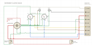
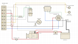
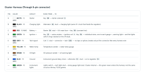
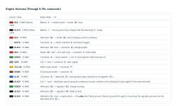
It needs some wiring rehab from years of previous owners turning the wiring into a complete rats nest. When I pulled up the manual I noticed that the factory wiring diagram is a bit confusing and difficult to understand for some. Thankfully I work in the Marine and power sports industry specializing in electrical so I was able to understand it pretty easily after a few head shakes. So to make it easier for people who may not be the most electrically inclined I made up the following drawings based specifically on the factory manual diagram and wiring call outs to give to my brother so that he can use it to fix his boat, but I also wanted to share it here for anyone looking for a much easier to understand version.
All of it is properly color coded to the VP specs of the era, wire sizes converted to modern AWG sizes.
And if anyone is interested, I have the same one drawn up, but with a Pertronix igniter conversion powered through a 40 Amp marine relay that is triggered by the factory resistance wire/Ballast Resistor connection in order to allow for a quick swap back to points and condenser in the event of an igniter module failure on water which would make it so that you could still get the boat started and make it back to the dock.
My brother owns a 1971 Chrysler Sport Fury 16 foot. That is powered by a VP 130C/250 Drive.
It needs some wiring rehab from years of previous owners turning the wiring into a complete rats nest. When I pulled up the manual I noticed that the factory wiring diagram is a bit confusing and difficult to understand for some. Thankfully I work in the Marine and power sports industry specializing in electrical so I was able to understand it pretty easily after a few head shakes. So to make it easier for people who may not be the most electrically inclined I made up the following drawings based specifically on the factory manual diagram and wiring call outs to give to my brother so that he can use it to fix his boat, but I also wanted to share it here for anyone looking for a much easier to understand version.
All of it is properly color coded to the VP specs of the era, wire sizes converted to modern AWG sizes.
And if anyone is interested, I have the same one drawn up, but with a Pertronix igniter conversion powered through a 40 Amp marine relay that is triggered by the factory resistance wire/Ballast Resistor connection in order to allow for a quick swap back to points and condenser in the event of an igniter module failure on water which would make it so that you could still get the boat started and make it back to the dock.
Attachments
Last edited:

