Backup Bilge Pump

62cruiserinc

Petty Officer 1st Class
Joined
Oct 30, 2009
Messages
295
I have a 19811 Sea Ray 26' Sundancer.

The bilge normally gets little water into it. There is a bilge pump now with a float switch that came with the boat when I bought it a few years ago.

I want to add a high-capacity backup pump in case the original fails or something big happens to let more water into the bilge (bellows leak?).

The backup would be installed so it doesn't come on unless the original failed and the water level goes above the normal trigger level.

I am looking at the Johnson heavy-duty 2200 GPH pump and the Johnson solid-state switch that doesn't have a float.

Since this would rarely come on (I hope!), it would lay dormant for long periods of time, so I would activate it every so often so things don't go bad from sitting too long.

Any comments on my plan?

Steve
 

Alumarine

Captain
Joined
Feb 22, 2005
Messages
3,738
Sounds like a good plan. I have 2 auto pumps.
Will you run a separate discharge line?
 

62cruiserinc

Petty Officer 1st Class
Joined
Oct 30, 2009
Messages
295
Sounds like a good plan. I have 2 auto pumps.
Will you run a separate discharge line?

The original pump line is too small, I think. If I tee into it, the pump output would be choked down from going through a small line.

I need to look and see where I might be able to tee into a bigger line. There are a bunch of drain and discharge line everywhere (above the waterline) on my boat. I really didn't want to put another thru-hull if I can avoid it.

Steve
 

dingbat

Supreme Mariner
Joined
Nov 20, 2001
Messages
16,313
The original pump line is too small, I think. If I tee into it, the pump output would be choked down from going through a small line.

I need to look and see where I might be able to tee into a bigger line. There are a bunch of drain and discharge line everywhere (above the waterline) on my boat. I really didn't want to put another thru-hull if I can avoid it.

Steve
To run two pumps and get anywhere near rated capacity you need separate and appropriately sized drain lines for each pump.

No reductions, No corrugated hose, etc. Read installation instructions on the box in full. Head pressures are low. (volume verse pressure) Figure on getting 55-60% rated flow when all is said and one

In reality, a bilge pump just isn't going to keep up. Just about any hull breech (thru hull, bellows, cooling hose, etc.) will quickly overwhelm a bilge pump. Carry a set of emergency hull plugs as a backup plan.
 

gm280

Supreme Mariner
Joined
Jun 26, 2011
Messages
14,605
Remember, the size of the outlet fitting on the bilge pump is only part of the issue. The longer the hose attached has a lot to do with the ability to pump the capability of the pump. So a large outlet hose with the shortest distance will give you more gallons per hour capability. "T" 'ing into any other hose, will certainly keep the GPH down. Just some info.
 

62cruiserinc

Petty Officer 1st Class
Joined
Oct 30, 2009
Messages
295
The pump has an output port for a 1 1/8" hose.

I was planning to tee into a larger diameter hose very close to the through-hull fitting, so flow restriction would be minimal. Actually not a tee but a y-fitting so the flow doesn't have to make a 90 degree turn.

There are some big hoses through-hull right near where I want to put the backup pump.

Has anyone used the "solid-state-sensor" switches that don't use any moving parts instead of the usual float switch? How well do they work?

Steve
 

mike_i

Ensign
Joined
Jun 28, 2017
Messages
958
dingbat is 100% correct. I would not tee any connection. I run two separate bilge pumps with separate discharge hoses and power supply. When you NEED to pump water you want to pump maximum water at maximum rate.

To run two pumps and get anywhere near rated capacity you need separate and appropriately sized drain lines for each pump.

No reductions, No corrugated hose, etc. Read installation instructions on the box in full. Head pressures are low. (volume verse pressure) Figure on getting 55-60% rated flow when all is said and one

In reality, a bilge pump just isn't going to keep up. Just about any hull breech (thru hull, bellows, cooling hose, etc.) will quickly overwhelm a bilge pump. Carry a set of emergency hull plugs as a backup plan.
 

gm280

Supreme Mariner
Joined
Jun 26, 2011
Messages
14,605
The pump has an output port for a 1 1/8" hose.

I was planning to tee into a larger diameter hose very close to the through-hull fitting, so flow restriction would be minimal. Actually not a tee but a y-fitting so the flow doesn't have to make a 90 degree turn.

There are some big hoses through-hull right near where I want to put the backup pump.

Has anyone used the "solid-state-sensor" switches that don't use any moving parts instead of the usual float switch? How well do they work?

Steve

Yes and no on the solid state sensors. I have never bought such a sensor. But I have made a few of them in my days and used them exclusively on every boat I owned but my first boat. Not much to them. Two probes that once water touches them it triggers a transistor circuit to switch on a relay to drive the pump. So the possibility of the two probes getting clogged with debris is just about nil. I have a very simple circuit schematic diagram if you are up to making a PC board and such.
 

62cruiserinc

Petty Officer 1st Class
Joined
Oct 30, 2009
Messages
295
Yes and no on the solid state sensors. I have never bought such a sensor. But I have made a few of them in my days and used them exclusively on every boat I owned but my first boat. Not much to them. Two probes that once water touches them it triggers a transistor circuit to switch on a relay to drive the pump. So the possibility of the two probes getting clogged with debris is just about nil. I have a very simple circuit schematic diagram if you are up to making a PC board and such.

Actually, I'm an electrical engineer and design circuits all the time for work, so I'm reluctant to do that for home since I do it at work all day:).

I also know that the reliability of the circuit depends on the components used, the PCB, sealing out water,etc. There is no way for me to know how good or bad the circuits are inside the purchased switch, but it's probably a "lowest-bidder" type of thing. Like the unreliable electronics on all my new appliances. That's why I was asking if anyone actually used one that they bought.

I'm still undecided between a float switch and an electronic one.

Steve
 

Tassie 1

Chief Petty Officer
Joined
Apr 13, 2018
Messages
584
No on the switches,

But l have three auto bilge pumps on my 30 ft fb cruiser
bow
Mid boat
Stern
3 batteries....2 start, one large house,

And a manual hand operated pump bolted in as well


There's two spare 12 volt bilge pumps ( one unopened from new ) in storage cupboards
And buckets

Just in case...


Boat does collect rainwater ( just had 4 days of rain ) while on the mooring and some sw ingress while on the move
 

gm280

Supreme Mariner
Joined
Jun 26, 2011
Messages
14,605
Actually, I'm an electrical engineer and design circuits all the time for work, so I'm reluctant to do that for home since I do it at work all day:).

I also know that the reliability of the circuit depends on the components used, the PCB, sealing out water,etc. There is no way for me to know how good or bad the circuits are inside the purchased switch, but it's probably a "lowest-bidder" type of thing. Like the unreliable electronics on all my new appliances. That's why I was asking if anyone actually used one that they bought.

I'm still undecided between a float switch and an electronic one.

Steve

Okay I will post MY schematic diagram. I did this in my boat project before. It isn't like some secret circuit. And since it is so simple, the reliability is way up there. In the many years I've used this circuit, I never once ever had any problems.

As you can see, it is basically a darlington configuration pair for very high gain. Simple NPN general transistors of basically any type. And you can also see R1 and R3 are inserted so that if for some reason the probes short to ground, the current draw is nothing to worry about. No smoke or mirrors, just a simple high gain relay driver. And the relay can be most any type that can handle the pump current. Also the diode is there for the reverse EMF, to protect both the transistor and relay coil.

Simple if you want to try it.
 

Attachments

  • Auto Bilge Switch.gif
    Auto Bilge Switch.gif
    22.4 KB · Views: 2

froggy1150

Master Chief Petty Officer
Joined
Nov 3, 2017
Messages
860
Cool. Simple. And I have all that stuff in my solid state stash. But what material for probes? 1/8 stainless rod? How far apart ..... also 1/8?
 

gm280

Supreme Mariner
Joined
Jun 26, 2011
Messages
14,605
Cool. Simple. And I have all that stuff in my solid state stash. But what material for probes? 1/8 stainless rod? How far apart ..... also 1/8?

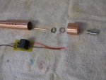
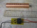
Actually the distance of the probes is really not too important, within reason. I think I have mine about ~1 1/2" or less in everything I've used them on. My present setup I used just bare copper wire for the probes. But again anything metal should work. Stainless steel would do fine. I used either 12 gauge or 10 gauge solid house wire to make the probes from. And I used a piece of copper tube for one probe with the solid copper wire inside in the center, for the other. I drill some small holes in the copper tube for the water to flow through but keep debris out. Here is my setup.

You can see I used a standard stainless steel BNC type connector to attach everything to the circuit in the bow section. Easy and maintenance free...
 

Attachments

  • Water Probe Parts.jpg
    Water Probe Parts.jpg
    282.7 KB · Views: 0
  • Water Probe setup for assembly.jpg
    Water Probe setup for assembly.jpg
    351.7 KB · Views: 0
  • Water Probe assembled with circuit.jpg
    Water Probe assembled with circuit.jpg
    291.7 KB · Views: 0
Top