PondTunes
Petty Officer 1st Class
- Joined
- Jun 7, 2007
- Messages
- 387
There are many different configurations of engines, number of batteries, and how they are hooked up. This guide should help explain how switch setups are connected to banks of batteries & the charging systems that keep them powered.
Points to keep in mind:
1) NEVER Ever switch a On/Off disconnect or OFF-1-2-BOTH switch to the OFF position with the engine running or you will end up with a dead charging system. Alternators do not like being disconnected while running. If you are going to be switching them at all while the engine is running (ie 1-2-both) be 100% sure that they are make-before-break design!
2) Always use a meter / circuit tester to verify circuits a short circuit or reverse polarity can be just as rough on your charging system as disconnecting it while running.
3) A repair manual for your engine is a great, inexpensive investment that will tell you what every wire, nut and bolt are for that is connected to your engine.
SINGLE OUTBOARD ENGINE CHARGING SETUP:
This is normally a very simple setup consisting of ONE engine and ONE battery. Outboard engine alternators normally do not have the output of marine inboard engines and the output should be checked before considering adding batteries to the system. Keep in mind these systems are designed to keep your batteries topped of and NOT to recharge dead batteries..
That being said you should take into account the average current draw per hour of your accessories to see if your engine is even capable of supporting your loads. Say for example If you run a trolling motor, depth finder, bilge & lights and lets just say that that works out to 15 amps off of your battery. A small outboard may have a 10 amp charging system (meaning it can put 10 amps back into a battery per hour) Thus it would take 1.5 hours at WOT to fully replace what you used. Charging systems on outboards vary a lot with 35 amp systems being available on newer, larger outboards so it is important to find out exactly what you are dealing with. Keep in mind if you happen to pick up a big group 27 battery with say 90 amp/hour reserve it would take even the 35 amp system about 2 1/2 hours at WOT to recharge it from a discharged state!!!
An alternative to using a dual battery setup on an outboard powered boat one could consider having a large deep cycle battery connected to the high draw loads such as stereo amplifiers or trolling motors. These items would be completely isolated from the starting system/circuits and would be the only things connected to the spare battery. Our big group 27 battery with 90 amp/hour reserve would last for about 6 hours if we maintained a 15 amp draw on it! These accessory batteries would be charged using a maintainer or shore charger each time the boat is brought in or brought home. They could also be used in a pinch if the main battery were to fail for some reason.
The backup battery:

In the above image (Fig #1) we have our outboard engine, battery #1 & battery #2 and a OFF-1-2-BOTH Switch (A). Note post (C) on Switch (A) it is known as our common, ie if the switch is set to 1 or 2 then common will be connected to 1 or 2. Our house load & engine is connected to the common post (C) on switch (A). Lets say battery #1 is a normal marine cranking battery and battery #2 is a dual purpose starting/deep cycle. Proper operation of this system would be to use selection #1 for cranking the boat, then driving to our fishing hole. When we get to our fishing/swimming hole we shut down the engine and move switch (A) to position 2. This disconnects our main starting battery and allows us to run the trolling motor and all other house circuits off of battery #2.
If we manage to totally drain battery #2 dead we are still ok because battery #1 has plenty of charge to get us going again. Once it's time to go or move to a different spot battery #2 should be selected while the engine is running to charge it. The BOTH setting should NOT be used on an outboard to attempt to charge both batteries in my option because they just don't have enough charging power to even dent two batteries unless you have a very long ride at WOT ahead of you. In essence this setup acts like a single battery system with a spare battery in the boat just in case you run one dead.
SINGLE INBOARD ENGINE SETUP
If we change gears and look at figure #1 again except with an inboard engine with a higher output charging system we can get a bit more functionality out of our switches. Marine alternators much like car alternators normally produce much more charging power than outboards. High output upgrades are also available in as much as 100-250 amp configurations. These alternators are capable of keeping the charge up on multiple batteries. We could also use the BOTH setting while underway to top off both batteries. However; as with the outboard engine you should look at your current draw/alternator output to decide how much your charging system can handle.
There are some drawbacks to this setup however. Lets say our operator had Switch (A) in the BOTH setting to charge his batteries. It is possible that if he sat long enough he could drain BOTH batteries while fishing/swimming or whatever. There is also the possibility of if one battery happens to bad it could drain the other battery while in the BOTH setting... He has to remember to switch the switch from BOTH to a single battery while anchored. For someone who has always had this setup it probably will never happen, if you add this setup to your boat it's likely that you could forget because it's a new step you have to follow.
SINGLE INBOARD ENGINE SETUP (AUTOMATIC)
This setup involves a special switch/relay that automatically connects/disconnects the batteries to the charging system. It simply takes the remembering to switch step out of the equation and improves on an otherwise good setup.
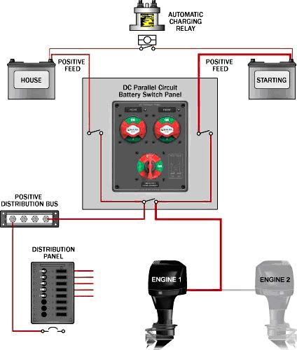
Fig #2 - 1 Engine w ACR

What we see here in Fig #2 is that Switch (A) has been replaced with a special dual circuit switch that works much like switch (A) but has four poles. The house loads are connected to pole 1
The charging system is connected to pole 2.
Battery #1 is connected to pole 3 and is our starting battery
Battery #2 is connected to pole 4 and is our house battery
An ACR or automatic charging relay is connected to the positive post of both battery #1 and battery #2. This relay is responsible for connecting/disconnecting the batteries in parallel and prevents the house battery from discharging the cranking battery.
Once installed the dual circuit switch (D) will disconnect both batteries when in the OFF position, and connect them when in the ON setting. It also has a COMBINE setting for emergency use in case something happens to our cranking battery. In an emergency is the ONLY time the switch should be changed to combine, the ACR handles charging the house/charging batteries without us doing anything.
When we crank up and get underway the ACR closes the connection between battery #1 & #2 and allows both to charge. Once we shut down the engine the ACR detects that there is no charge present and breaks the connection between the batteries.
Two Engines Two Batteries
This setup would be the same regardless if the engines were inboard or outboard. Normally these setups will be found with two OFF-1-2-BOTH switches wired up to allow either battery or both to crank either engine. The house battery #3 is not recommended for outboard setups.

This setup gets a little more complicated to explain so please refer to figure #3 as you read along. Under normal use the Switch (A) would be set to position 1, Switch (B) would be set to position 2. Battery #1 would crank the starboard engine & supply power to the house circuits. Battery #2 would serve only to crank the Port engine. While underway no switching is required, battery #1 is charged by the starboard engine & battery #2 is charged by the port engine.
When the engines are stopped the house circuits run off of battery #1. If we were to drain battery #1 we could simply move switch (A) to position 2 and use battery #2 to crank the starboard engine. Likewise if something were to happen to battery #2 and it died we could use position 1 on switch (B) to use battery #1 to crank the port engine! (wow that was complicated)
The BOTH setting really does not have much use in this setup the switches should never be left in the both position as they could leave us with two dead batteries. BOTH could possibly be used in the event that say the alternator on the port engine failed. If so Switch (B) would be set to OFF and Switch (A) would be set to BOTH... (WARNING! Never Ever Ever set a switch to OFF with the engine running or you WILL have a failed alternator!)
With Switch (A) set to BOTH and (B) set to OFF the starboard engine would be charging both batteries and both batteries would be used to crank both engines.
Figure #3 also shows an optional house battery #3 (Not recommended for outboard engines!). A simple OFF/ON Disconnect switch (D) could be used when anchored to run the house circuits and ensure that battery #1 and battery #2 were fresh for cranking. With the switch in the ON position battery #1 and Battery #3 would supply the house circuits & be charged by the starboard engine. With switch (D) in the OFF setting only battery #3 would supply the house circuits with power.
As an alternative a ACR - Automatic Charging Relay or battery isolator could be put in place of switch (D) for automatic isolation of the house circuits.
Points to keep in mind:
1) NEVER Ever switch a On/Off disconnect or OFF-1-2-BOTH switch to the OFF position with the engine running or you will end up with a dead charging system. Alternators do not like being disconnected while running. If you are going to be switching them at all while the engine is running (ie 1-2-both) be 100% sure that they are make-before-break design!
2) Always use a meter / circuit tester to verify circuits a short circuit or reverse polarity can be just as rough on your charging system as disconnecting it while running.
3) A repair manual for your engine is a great, inexpensive investment that will tell you what every wire, nut and bolt are for that is connected to your engine.
SINGLE OUTBOARD ENGINE CHARGING SETUP:
This is normally a very simple setup consisting of ONE engine and ONE battery. Outboard engine alternators normally do not have the output of marine inboard engines and the output should be checked before considering adding batteries to the system. Keep in mind these systems are designed to keep your batteries topped of and NOT to recharge dead batteries..
That being said you should take into account the average current draw per hour of your accessories to see if your engine is even capable of supporting your loads. Say for example If you run a trolling motor, depth finder, bilge & lights and lets just say that that works out to 15 amps off of your battery. A small outboard may have a 10 amp charging system (meaning it can put 10 amps back into a battery per hour) Thus it would take 1.5 hours at WOT to fully replace what you used. Charging systems on outboards vary a lot with 35 amp systems being available on newer, larger outboards so it is important to find out exactly what you are dealing with. Keep in mind if you happen to pick up a big group 27 battery with say 90 amp/hour reserve it would take even the 35 amp system about 2 1/2 hours at WOT to recharge it from a discharged state!!!
An alternative to using a dual battery setup on an outboard powered boat one could consider having a large deep cycle battery connected to the high draw loads such as stereo amplifiers or trolling motors. These items would be completely isolated from the starting system/circuits and would be the only things connected to the spare battery. Our big group 27 battery with 90 amp/hour reserve would last for about 6 hours if we maintained a 15 amp draw on it! These accessory batteries would be charged using a maintainer or shore charger each time the boat is brought in or brought home. They could also be used in a pinch if the main battery were to fail for some reason.
The backup battery:
In the above image (Fig #1) we have our outboard engine, battery #1 & battery #2 and a OFF-1-2-BOTH Switch (A). Note post (C) on Switch (A) it is known as our common, ie if the switch is set to 1 or 2 then common will be connected to 1 or 2. Our house load & engine is connected to the common post (C) on switch (A). Lets say battery #1 is a normal marine cranking battery and battery #2 is a dual purpose starting/deep cycle. Proper operation of this system would be to use selection #1 for cranking the boat, then driving to our fishing hole. When we get to our fishing/swimming hole we shut down the engine and move switch (A) to position 2. This disconnects our main starting battery and allows us to run the trolling motor and all other house circuits off of battery #2.
If we manage to totally drain battery #2 dead we are still ok because battery #1 has plenty of charge to get us going again. Once it's time to go or move to a different spot battery #2 should be selected while the engine is running to charge it. The BOTH setting should NOT be used on an outboard to attempt to charge both batteries in my option because they just don't have enough charging power to even dent two batteries unless you have a very long ride at WOT ahead of you. In essence this setup acts like a single battery system with a spare battery in the boat just in case you run one dead.
SINGLE INBOARD ENGINE SETUP
If we change gears and look at figure #1 again except with an inboard engine with a higher output charging system we can get a bit more functionality out of our switches. Marine alternators much like car alternators normally produce much more charging power than outboards. High output upgrades are also available in as much as 100-250 amp configurations. These alternators are capable of keeping the charge up on multiple batteries. We could also use the BOTH setting while underway to top off both batteries. However; as with the outboard engine you should look at your current draw/alternator output to decide how much your charging system can handle.
There are some drawbacks to this setup however. Lets say our operator had Switch (A) in the BOTH setting to charge his batteries. It is possible that if he sat long enough he could drain BOTH batteries while fishing/swimming or whatever. There is also the possibility of if one battery happens to bad it could drain the other battery while in the BOTH setting... He has to remember to switch the switch from BOTH to a single battery while anchored. For someone who has always had this setup it probably will never happen, if you add this setup to your boat it's likely that you could forget because it's a new step you have to follow.
SINGLE INBOARD ENGINE SETUP (AUTOMATIC)
This setup involves a special switch/relay that automatically connects/disconnects the batteries to the charging system. It simply takes the remembering to switch step out of the equation and improves on an otherwise good setup.
Fig #2 - 1 Engine w ACR
What we see here in Fig #2 is that Switch (A) has been replaced with a special dual circuit switch that works much like switch (A) but has four poles. The house loads are connected to pole 1
The charging system is connected to pole 2.
Battery #1 is connected to pole 3 and is our starting battery
Battery #2 is connected to pole 4 and is our house battery
An ACR or automatic charging relay is connected to the positive post of both battery #1 and battery #2. This relay is responsible for connecting/disconnecting the batteries in parallel and prevents the house battery from discharging the cranking battery.
Once installed the dual circuit switch (D) will disconnect both batteries when in the OFF position, and connect them when in the ON setting. It also has a COMBINE setting for emergency use in case something happens to our cranking battery. In an emergency is the ONLY time the switch should be changed to combine, the ACR handles charging the house/charging batteries without us doing anything.
When we crank up and get underway the ACR closes the connection between battery #1 & #2 and allows both to charge. Once we shut down the engine the ACR detects that there is no charge present and breaks the connection between the batteries.
Two Engines Two Batteries
This setup would be the same regardless if the engines were inboard or outboard. Normally these setups will be found with two OFF-1-2-BOTH switches wired up to allow either battery or both to crank either engine. The house battery #3 is not recommended for outboard setups.
This setup gets a little more complicated to explain so please refer to figure #3 as you read along. Under normal use the Switch (A) would be set to position 1, Switch (B) would be set to position 2. Battery #1 would crank the starboard engine & supply power to the house circuits. Battery #2 would serve only to crank the Port engine. While underway no switching is required, battery #1 is charged by the starboard engine & battery #2 is charged by the port engine.
When the engines are stopped the house circuits run off of battery #1. If we were to drain battery #1 we could simply move switch (A) to position 2 and use battery #2 to crank the starboard engine. Likewise if something were to happen to battery #2 and it died we could use position 1 on switch (B) to use battery #1 to crank the port engine! (wow that was complicated)
The BOTH setting really does not have much use in this setup the switches should never be left in the both position as they could leave us with two dead batteries. BOTH could possibly be used in the event that say the alternator on the port engine failed. If so Switch (B) would be set to OFF and Switch (A) would be set to BOTH... (WARNING! Never Ever Ever set a switch to OFF with the engine running or you WILL have a failed alternator!)
With Switch (A) set to BOTH and (B) set to OFF the starboard engine would be charging both batteries and both batteries would be used to crank both engines.
Figure #3 also shows an optional house battery #3 (Not recommended for outboard engines!). A simple OFF/ON Disconnect switch (D) could be used when anchored to run the house circuits and ensure that battery #1 and battery #2 were fresh for cranking. With the switch in the ON position battery #1 and Battery #3 would supply the house circuits & be charged by the starboard engine. With switch (D) in the OFF setting only battery #3 would supply the house circuits with power.
As an alternative a ACR - Automatic Charging Relay or battery isolator could be put in place of switch (D) for automatic isolation of the house circuits.