Best battery setup for solar charging while in storage

Zippady

Cadet
Joined
Jan 2, 2020
Messages
23
Setup - boat has two hybrid batteries connected with a blue sea systems switch and VSR. Even though weather can be ok year around because of work boat use can be sporadic. I used to take the batteries out to keep trickle charged but I’m getting lazy. I have a small 40w solar panel and suitable charger so my new plan is to leave the batteries in and hook up the solar charger when it is parked, the boat has a cover over it so a fixed panel isn’t suitable but the batteries and charger have Anderson plugs on them so it is easy to plug in and put the panel on the roof on the cover.

To connect the charger I could
1 - plug the charger into one of the batteries and let the installed VSR put them in parallel when the solar is working however, so that I can isolate the batteries the VSR I connected after the switch so for this to work I would need to turn the main power switch on. All the accessories are individually switched so the only thing with power (I think) would be the trim tilt on the outboard.

2 - make a parallel plug into the solar charger and hook it directly into both batteries, the down side to this is that they would be in parallel whenever they are plugged in without the VSR separating them when not being charged, my concern with this is that if one battery starts to go it will drain the other.

Questions
1 - what is the best way to connect to both batteries to charge?
2 - is there an issue leaving the main switch on and power to the trim/tilt circuit?
3 - is there an issue leaving the batterie connected in parallel when the boat is parked?
 

dingbat

Supreme Mariner
Joined
Nov 20, 2001
Messages
16,338
I have the Blue Seas ACR setup with the charge relay connected between the batteries, independent of the switch. The switch is on/off/ both functionality.

To charge both batteries, I simply connect the charger to the starting battery terminal (closest to charger) and let the ACR do its job.

Don’t understand how your system is wired if you have a switch on the VSR circuit
 
Last edited:

Zippady

Cadet
Joined
Jan 2, 2020
Messages
23
Thinking about it now my setup is the not recommended version. The VSR sits directly above the switch (off, on, both switch). The battery inputs are on the bottom terminals on the switch, on the top terminals as well as the outputs are very short cables with 60amp CBs going to the VSR. So turning the switch off disconnects VSR from the system.

according to the instructions it is not recommend because of voltage drop. I figure the cables wouldn’t get any shorter and it is using the thick starting leads anyway.
 

Zippady

Cadet
Joined
Jan 2, 2020
Messages
23
The local shop had a sale on some old model VSRs so i ended up picking up another and adding it to the solar charger. Now both batteries are being charged with the battery switch off
 

dingbat

Supreme Mariner
Joined
Nov 20, 2001
Messages
16,338
Thinking about it now my setup is the not recommended version. The VSR sits directly above the switch (off, on, both switch). The battery inputs are on the bottom terminals on the switch, on the top terminals as well as the outputs are very short cables with 60amp CBs going to the VSR. So turning the switch off disconnects VSR from the system.

according to the instructions it is not recommend because of voltage drop. I figure the cables wouldn’t get any shorter and it is using the thick starting leads anyway.
Now you really have me scratching my head....I don't see how putting the VSR between the switch outputs would even work. I can see how installing the ACR between the battery inputs might work

The wire from the the motor's charging circuit is typically connected directly to the positive terminal battery one. The charge relay is then wired directly between the positive terminals of the two batteries as shown below.

On my install, the switch is mounted next to battery 1 (ignition). The ACR is mounted next to Battery 2 (House) which is roughly 7 feet away. Used #4 wire and fused at 80 amps.

attachment.php
 
Last edited:

Zippady

Cadet
Joined
Jan 2, 2020
Messages
23
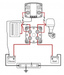
This is my setup, the switch is always on when the motor is running therefore charging so the switched outputs are always connected to the respective batteries. The VSR is mounted directly above the switch in the centre of the transom with the batteries on either side of the boat. The VSR wires are about 6 inches long with 60amp fuses on each side.

boat battery switch.png
 
Last edited:

dingbat

Supreme Mariner
Joined
Nov 20, 2001
Messages
16,338
This is my setup, the switch is always on when the motor is running therefore charging so the switched outputs are always connected to the respective batteries. The VSR is mounted directly above the switch in the centre of the transom with the batteries on either side of the boat. The VSR wires are about 6 inches long with 60amp fuses on each side.


That makes absolutely no sense to me....

Where is the alternator / stator wire connected to the system? It's should be connected to the "starting" battery
 
Last edited:

Zippady

Cadet
Joined
Jan 2, 2020
Messages
23
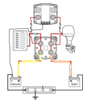
With the battery switch off both of the inputs on the switch are live from the respective batteries

switch off.png

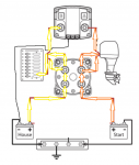
With the switch on, the house battery powers the accessories and the start battery is ready to start the motor, each side of the ACR is now live from the respective batteries but not connected because the voltage is too low.
switch on motor off.png

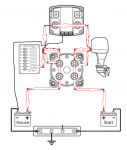
When the motor is started the alternator outputs a voltage higher than the batteries, the start battery is now charged down the same line that was used to start the motor, the increased voltage on the ACR on the B side now activates the ACR and connects A-B, with the ACR active the battery switch is effectively in parallel through the ACR. The accessories are now powered by the alternator and the house battery is charged by the alternator down the same cable that is used to power the accessories.
motor on charging.png
 
Top