Re: Bilge Pump wiring/switch
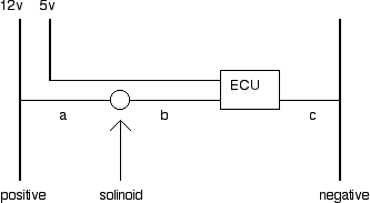
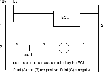
Let see if we can find any truth behind the madness. A blower by any name is a motor with variable speed controlled by two of the common typea . A rheostat or variable resistor adjust the power going to the motor thus increasing or decreasing rotation speed as desired. <br /><br />1) For the fact that a rheostat or variable resistor is used, we can conclude the switching is done on the positive side. Such devices are not designed for use on the negative line.<br /><br />2) If the switching is done on the negative side, the following observations can be made. At any moment as long as the battery is good and connected to the appropriate leads the blower motor is "hot" on the positive lead of the motor regardless what position the ignition key or the control switch is in. By this logic, the key is not used in the switching on the motor in-conjunction to the variable speed control switch . So the following must be true.<br /><br />With the ignition key in the off position the blower should run when ever the variable speed control switch is activated. <br /><br />With the ignition key and the variable speed switch in the off position, there will be voltage between the positive lead of the blower motor and to any grounded parts of the car.<br /><br />With the ignition key on (second position in most cars) there should be no voltage on either side of the variable speed switch.<br /><br />I can give you 99 more statements similar to the above. They all must be true if the switching is done on the negative side of the motor, but time does not allow. So let us move on to the next item.<br /><br />Fuel Injectors function similar to door bells. Inside an injector, a solenoid sits slightly in the middle of a coil of wire. When activated, the coil creates a magnetic field lifting the solenoid up allowing gasoline to escape into the engine camber.<br />The electrical unit in question is the coil of wire. By definition (line ladder logic), a continuous length of wire is determined by it source of origin to the point of termination (see diagram A). if more than one load is in series, the positive wire is identified to the point of termination of the last load. Imagine a 12 inch piece of wire in your hand. One end is connected to the 12v positive side of a battery. Then make a coil loosely around your index finger. Now check to see if voltage presents before and after the coil. The answer is yes therefore the length of wire thru the coil is positive. In-contrast a negative wire is determine by the source to the first point of termination. In this case the ECU is the first point of junction. Clearly the section of wires at point (A) and (B) (see diagram) are positive. <br /><br />As mentioned before sometime the rules of the game is more important than the game. I may want to add that you are not wrong in assuming the switching is on the negative side.<br /><br />

Let see if we can find any truth behind the madness. A blower by any name is a motor with variable speed controlled by two of the common typea . A rheostat or variable resistor adjust the power going to the motor thus increasing or decreasing rotation speed as desired. <br /><br />1) For the fact that a rheostat or variable resistor is used, we can conclude the switching is done on the positive side. Such devices are not designed for use on the negative line.<br /><br />2) If the switching is done on the negative side, the following observations can be made. At any moment as long as the battery is good and connected to the appropriate leads the blower motor is "hot" on the positive lead of the motor regardless what position the ignition key or the control switch is in. By this logic, the key is not used in the switching on the motor in-conjunction to the variable speed control switch . So the following must be true.<br /><br />With the ignition key in the off position the blower should run when ever the variable speed control switch is activated. <br /><br />With the ignition key and the variable speed switch in the off position, there will be voltage between the positive lead of the blower motor and to any grounded parts of the car.<br /><br />With the ignition key on (second position in most cars) there should be no voltage on either side of the variable speed switch.<br /><br />I can give you 99 more statements similar to the above. They all must be true if the switching is done on the negative side of the motor, but time does not allow. So let us move on to the next item.<br /><br />Fuel Injectors function similar to door bells. Inside an injector, a solenoid sits slightly in the middle of a coil of wire. When activated, the coil creates a magnetic field lifting the solenoid up allowing gasoline to escape into the engine camber.<br />The electrical unit in question is the coil of wire. By definition (line ladder logic), a continuous length of wire is determined by it source of origin to the point of termination (see diagram A). if more than one load is in series, the positive wire is identified to the point of termination of the last load. Imagine a 12 inch piece of wire in your hand. One end is connected to the 12v positive side of a battery. Then make a coil loosely around your index finger. Now check to see if voltage presents before and after the coil. The answer is yes therefore the length of wire thru the coil is positive. In-contrast a negative wire is determine by the source to the first point of termination. In this case the ECU is the first point of junction. Clearly the section of wires at point (A) and (B) (see diagram) are positive. <br /><br />As mentioned before sometime the rules of the game is more important than the game. I may want to add that you are not wrong in assuming the switching is on the negative side.<br /><br />


