Boat weight distribution on a bunk lift (?)

harringtondav

Commander
Joined
May 26, 2018
Messages
2,450
I'm getting closer to buying a larger, heavier boat. Current boat is on a marine rail lift that I designed and built for that boat. I'm asking my structural engineer son to pay back some of the tuition I paid to analyze my rail system's load limits.

That will answer some questions, with pretty good science, but not all. The boat sets on a bunk carriage with a 10' spread between wheel pairs. This places the max loads centered between the 5' support spans of the rail channel. Point loading from each front and rear wheel is the unknown. The transom is essentially over the rear carriage wheels.

Sooo, the rest will be guesstimating. I used a 70/30% guess for front/rear weight distribution originally, which has worked fine. The new boat will overhang the front wheels by at least 2' (as in 2footitus).

Any opinions on weight distribution of a 20' I/O BR from transom to 10' forward? 4.5 Merc I/O in a 3300# dry weight boat.
Invoking tpenfield.
 

tpenfield

Moderator
Staff member
Joined
Jul 18, 2011
Messages
18,281
Got any pictures/diagrams of the rail system? I would assume that you can achieve a desired weight balance by adjusting where you place the boat along the 10' bunk carriage, giving a certain amount of overhang bow/stern. (right?)

Are you looking to see if it will work at all or is there a desired weight distribution between the wheel pairs?
 

Scott Danforth

Grumpy Vintage Moderator still playing with boats
Staff member
Joined
Jul 23, 2011
Messages
50,599
need a sketch like Ted mentions

on this new boat, any idea where the fuel tank is? dry weight will have the CG in the aft 1/3, however fuel tank will help determine the rough CG

more importantly than your beams, how are you driving your current lift? if cable, are you 2:1 or 3:1 rig? gearbox ratio and torque limit?
 

Chris1956

Supreme Mariner
Joined
Mar 25, 2004
Messages
28,217
The motor+outdrive is going to be 1/3 of total weight of the boat, say 1100#. That is nearly all the way aft. The fuel tank usually sits just in front of the engine, and is the second heaviest single item(say 340#), when full.

The bow, despite being a BR is still pretty light. If you have ever driven a boat like that, you quickly realize that it is real aft heavy. I would expect weight distribution to be 35/65 front to rear, but that is a round guess. Put a wheel just behind the center of the motor, and you should be OK.

Also from the popular song, "Let them (the children) lead the way" and get your kid to work it.
 

dingbat

Supreme Mariner
Joined
Nov 20, 2001
Messages
16,453
Find a boat similar to the one under consideration sitting on a trailer. Note the center line of axle(s) relative to the boat.

CG of load would be ~10% forward of the centerline the two axles on tandem, leading edge of tire on a single axle trailer
 

mt2006

Cadet
Joined
Jul 6, 2016
Messages
23
Remember......if you get the Regal it has a stepped hull. Not sure whether that is relevant but thought I would mention.
 

Scott Danforth

Grumpy Vintage Moderator still playing with boats
Staff member
Joined
Jul 23, 2011
Messages
50,599
got an actual model number of the boat you are looking at? Call the companies Customer Service number and they will be able to give you the exact CG. Regal Marine Industries, Inc. 2300 Jetport Drive Orlando, FL 32809. 1-800-US-REGAL 1-407-851-4360
 

harringtondav

Commander
Joined
May 26, 2018
Messages
2,450
Got any pictures/diagrams of the rail system? I would assume that you can achieve a desired weight balance by adjusting where you place the boat along the 10' bunk carriage, giving a certain amount of overhang bow/stern. (right?)

Are you looking to see if it will work at all or is there a desired weight distribution between the wheel pairs?

I've got the design in PTC/Creo. It will take a bit to bring up the carriage assy and get a screen shot to share.

I bump the O/D against a stop bar at the back of the carriage to keep the transom over the rear bunk mounts and rear wheels. Much further ahead and the bunks start bending. 2X6" bunks. The front and rear bunk supports carry most of the boat. The bunks are more guide-ons than support. So the boat's position is mostly fixed. Stopping it more rearward would just increase the weight on those rear wheels.

I'm looking to see the max weight allowable with the 3 x 2.07 6061 structural aluminum channel supported at 5' intervals. 40K psi tensile. My +-2500# Larsen with fuel and gear gives zero deflection mid span at the rear wheels. So I'm trying to figure how much of the new boat's weight will be on those rear wheels. If I'm good, I'll need to determine how many passengers, and where in the boat, can ride the boat down to the water. No problems today with 4 passengers, but I may have to ride a bigger boat down myself and pick up passengers at my neighbors dock.

The Chaparall's dry weight is close to my Larson's, but not my first pick. I'm looking for a heavier boat to tame river chop and waves.
 

harringtondav

Commander
Joined
May 26, 2018
Messages
2,450
need a sketch like Ted mentions

on this new boat, any idea where the fuel tank is? dry weight will have the CG in the aft 1/3, however fuel tank will help determine the rough CG

more importantly than your beams, how are you driving your current lift? if cable, are you 2:1 or 3:1 rig? gearbox ratio and torque limit?

I'm driving a 60:1 right angle gear reducer with a 1.5 hp 240V Marathon industrial motor. Further reduced by a chain sprocket drive between the reducer and the traction winch. The 5/16 SS cable will still be well within it's working limit. I'm thinking I'll have to take a couple teeth off the drive sprocket to keep the amp load on the motor where it should be.
....the loads on the traction winch's bearings will increase by 50%. I need to see if they can take it.

I'll be looking at the boats in the next few weeks. None of the pics show a gas tank access panel (?!). Hopefully it's under the carpet/mat. ...guessing the front of the tank is in the rear 1/2 of the boat.
 

harringtondav

Commander
Joined
May 26, 2018
Messages
2,450
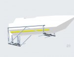
tpenfield Scott Danforth Here is a screen shot of the carriage assembly. A few parts are missing from the model, but I hope this helps. The "boat" shown is my 16' 9" OAL Larsen. The wheels are hard to see, but they are 6" flanged bridge crane trolley wheels under the bunk support structure. The new boat will overhang in front another 2' 9".

I can stretch the carriage w/o too much pain, if needed. The longer boat in the current set up will distribute more weight to the front carriage wheels. The carriage can handle it. ..don't know about the hull. But the boat won't be bouncing down the road. Just a nice slow lift out of the water.

As far as weight distribution the transom is directly over the rear carriage wheels. The front wheels/bunk supports are about 10' forward, with another 9' 6"' overhanging vs. 6' 9" today.

Pic of current boat on lift below.

Click image for larger version  Name:	Carriage assy.jpg Views:	1 Size:	39.9 KB ID:	10835340Click image for larger version  Name:	Larsen on lift.jpg Views:	1 Size:	109.3 KB ID:	10835341
 

tpenfield

Moderator
Staff member
Joined
Jul 18, 2011
Messages
18,281
OK, I can calculate you weights/forces if you would like. I assume the track stays at the approximate angle shown so that the boat stays level when raised out of the water.
 

harringtondav

Commander
Joined
May 26, 2018
Messages
2,450
OK, I can calculate you weights/forces if you would like. I assume the track stays at the approximate angle shown so that the boat stays level when raised out of the water.

Yes. The track rise/run is 1/5. Not perfect along it's length, but darned close. I need yield/elastic limit point loading mid span (5' span), point supports. I'll keep the loading safely w/in the elastic range to avoid long cycle work hardening of the aluminum channel.

I don't want to be a greedy beggar, but if you have the tools to generate a stress/strain chart, it would be helpful in knowing my safety factor. I guess an ASTM tensile chart will work also. I can get that. If the failure load exceeds the (boat+carriage weight)/2 at the point load, I'm good. If not I'll be back to guesstimating the front - rear weight distribution. Carriage weight 250# max. Dry boat 3400# max. Weight on rear wheels =?

And thanks. Son is stalling, saying he needs more detailed info. This is a simple beam calc. I don't need his boss's PE stamp on it. grmmph...ingrate. Thinking I'll 'break' the boat before his annual bud's weekend.

Data you probably already have, but I need to offer something: My channel is 3 X 2.07 6061
https://www.engineersedge.com/materials/american_standard_aluminum_channel__13662.htm
https://www.upmet.com/sites/default/files/datasheets/6061.pdf
 
Top