Charging system on Mercury 25 hp

Andig

Cadet
Joined
Aug 29, 2021
Messages
7
Hi! I've been wanting to get a charging system for my boat and was looking into it and I saw a lot of people said you need to get extra coils should you not have them. I have a 25 hp 2 stroke JET20 2000 pull start Mercury. Here is the serial number: OG982888 when I look at the preexisting electical system I don't see where a charging system would go in. I was on a live chat with someone from boats.net and they recommended me This. It looks like it's just an extra bundle of wires. In that case could I just add wires and a rectifier? I also feel like that's not everything I need and I asked the sales guy and he said on multiple occasions that's what you need and you don't need anything extra. Can someone help me out? And sorry my brain is all over the place right now.

To clarify: my engine is a 25 hp 2 stroke pull start Mercury jet from 2000 and I ordered This part and I want to know if that's what I need to get a charging system. Thank you!!
 

nola mike

Vice Admiral
Joined
Apr 22, 2009
Messages
5,444
Not knowing your serial number, I have a similar motor, electric start with a battery. I'd have to look up the parts to see if what if any difference there is, but you should be able to find an oem solution if your motor doesn't have what's necessary
 

Andig

Cadet
Joined
Aug 29, 2021
Messages
7
Hi! Sorry for such a late reply. I was waiting for an email saying I got a response.

The serial number for my motor is OG982888

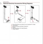
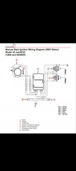
So I spoke to a few guys at Mercury and they sent me a few wiring diagrams from the service manual. Those are shown hereimage007.jpgScreenshot_20210905-092605.jpg

I requested the wiring diagram so I could try to figure out where to attach the charging system. So if any help could be provided that would be great. I have a good bit of questions to ask but I figured it would be easiest to see what everyone says because maybe I missed something simple.

The charging kit that Mercury sells for this motor only has two connectors that plug into the stator and into the rectifier. Wouldn't that take away the power for the spark? There I am with distracting questions.

Sorry to make this post so convoluted and confusing, I've been working at this for the past week and it's staring to get to me. Thank you for reading this over!
 

Andig

Cadet
Joined
Aug 29, 2021
Messages
7
I will say the optional electronics wiring diagram they sent me confused me further. I don't have the grey or yellow wires mentioned. Only the white/green and green/white coming from my stator. I contacted Mercury and they said that that's the only stator for my motor and it will work to charge. However I don't really believe that. Does the trigger produce its own power to make spark for the plugs? Or is that only get power from the stator. I'm just about to go test that by unplugging the stator and seeing if it still runs so I guess that will answer my question. But again my thought was to ask as a total beginner instead of trying to tell every bit I know and making it seem like I'd know something obvious when I wouldn't. Thanks!
 

Andig

Cadet
Joined
Aug 29, 2021
Messages
7
Once again here is an update. I just found a PDF of the service manual (I'm pretty sure it's the correct manual) which is awesome. Here is an excerpt from that.

The ignition system is an alternator driven capacitor discharge system. Major compo-
nents of the ignition system are the flywheel, stator, trigger coil, switch box, 2 ignition coils
and 2 spark plugs.
The flywheel has permanent magnets mounted in both the outer rim and the center hub.
The BLACK stator assembly is mounted below the flywheel and has a low speed (LS) and
a high speed (HS) capacitor charging coil. Low speed coil provides primary voltage to the
switch box from idle to approximately 2500 RPM. The high speed coil provides primary
voltage from 2000 RPM to the maximum RPM the outboard is capable of achieving.
The RED stator assembly is mounted below the flywheel and has only one capacitor
charging coil.
As the flywheel rotates, the magnets mounted in the flywheel outer rim pass the charging
coils creating voltage. This voltage charges the capacitor located in the switch box.
As the flywheel continues to rotate, the magnets in the center hub pass the trigger coil
creating AC voltage. This voltage turns on one of the two electronic switches (SCR) in the
switch box. A positive voltage pulse turns on the SCR switch associated with cylinder #1;
a negative voltage pulse turns on the SCR switch associated with cylinder #2.
The SCR switch discharges the stored capacitor voltage into the primary side of the re-
spective ignition coil. The ignition coil multiplies this voltage to a value high enough to
jump the spark plug gap -- 32000 volts for standard coils; 40000 volts for high energy coils.
This sequence occurs once per engine revolution for each cylinder
Spark timing on electronically advanced models is controlled internally by the switch box
with a fixed trigger.
Spark timing on mechanically advanced models is changed (advanced/retarded) by rotat-
ing the trigger coil which changes the trigger coil position in relation to the magnets in the
center hub of the flywheel.
The stop switch (or ignition switch) shorts the output of the stator to ground to stop the
engine on all models.

That makes me think it is impossible to add a charging system to this motor, I am pretty sure I have the red stator. Am I wrong in thinking that it won't work without an extra coil?
 

nola mike

Vice Admiral
Joined
Apr 22, 2009
Messages
5,444
I will say the optional electronics wiring diagram they sent me confused me further. I don't have the grey or yellow wires mentioned. Only the white/green and green/white coming from my stator. I contacted Mercury and they said that that's the only stator for my motor and it will work to charge. However I don't really believe that. Does the trigger produce its own power to make spark for the plugs? Or is that only get power from the stator. I'm just about to go test that by unplugging the stator and seeing if it still runs so I guess that will answer my question. But again my thought was to ask as a total beginner instead of trying to tell every bit I know and making it seem like I'd know something obvious when I wouldn't. Thanks!
Don't unplug things in a cdi system while running. The trigger doesn't provide power, it just tells the ignition module when to fire. Do you have the system in the second diagram, and the first diagrams are add ons? Lemme take a look at the diagrams...
 

Andig

Cadet
Joined
Aug 29, 2021
Messages
7
Okay! I will not do as such. And I do have the system in the first diagram. And that is correct the other diagram is just showing add-ons. However I don't think it's for my exact system.
 

nola mike

Vice Admiral
Joined
Apr 22, 2009
Messages
5,444
Ok, there isn't a functional difference between red and black stators, and they control ignition only. I don't see any of the optional kits in the manual, but the stock electric start system looks like the second option; I'm not sure when the other 2 would be used. The charging system is standalone, using a separate stair and wiring. Should be plug and play...
 

nola mike

Vice Admiral
Joined
Apr 22, 2009
Messages
5,444
Weird, that first diagram doesn't seem to do anything, just has an unused stator. If that's the case, all you need is the rectifier from what I see
 

Andig

Cadet
Joined
Aug 29, 2021
Messages
7
So when looking at the first diagram that shows the stator wires going into that isolation block. Which my motor does not have. And the wires coming from my stator are male and female while the connector for the rectifier is male and male. Which made me think it's the wrong setup somewhere. And you said you think the stator is unused?
 

nola mike

Vice Admiral
Joined
Apr 22, 2009
Messages
5,444
You said you had the system in the first diagram, which looks like it has an unused stator. The white/green wires are from the ignition stator. Again, totally separate from charging. If that's all you have then you need a kit with the stator and rectifier (or voltage reg, not sure what the difference is between kits 2 and 3).
 

Andig

Cadet
Joined
Aug 29, 2021
Messages
7
I have the system marked with the red stator that goes into the switch box. So with that said I would assume I can't add a charging system because Mercury told me that's the only stator that engine can fit and that it's all I need. However they don't know how to add a charging system. So I guess I will give up on the project. Thanks for looking at it!
 

nola mike

Vice Admiral
Joined
Apr 22, 2009
Messages
5,444
That's not correct. I think you misunderstood what they told you. I can only say that the ignition and charging are 2 different systems so many times...
 
Top