Diagnosing a Bad Stator

Mikebones1111

Recruit
Joined
Feb 24, 2015
Messages
2
Hello I have a 1986 140hp Johnson V4 (VRO removed)

My charging system seems to be weak when motor is running the volt gauge sits at 12v and that is confirmed by multimeter. I talked to a Power sports mechanic he asked me some questions if I had any melted plastic dripping from the stator windings which I do not as far as I can tell. He then recommended I try replacing the regulator/rectifier before replacing the stator. He said the previous owner could have fried it by jumping it from a running car. I replaced it and I saw only a slight gain in the voltage 12.5-13V when running not the 14+v I think I should be getting (If someone could confirm that because that is just a guess).

I am mechanically inclined and do most of my own work but another mechanic friend said it might be easier to pay to have the stator replaced. Has any one replaced their stator would you recommend doing it yourself again or paying to have it done. Can I check anything else to see if it solves the problem before diving into the stator?

Thank you,
 

tblshur

Senior Chief Petty Officer
Joined
Aug 24, 2011
Messages
688
mike, cdi electronics is a good place to start, they have step by step instructions. were you running the boat wot or just on muffs.the amount of charge in the battery may affect the voltage.replacing the stator is not abiggie , getting the flywheel off is the hardest part. IMO good luck:joyous:
 

gm280

Supreme Mariner
Joined
Jun 26, 2011
Messages
14,605
Welcome aboard Mike "welcome: nice to have you join us...

You really may not have any problem at all. At 13 volts (don't know if this was measured at the battery or idle either), but that is a respectable reading if it is at the battery and at idle. So before you go and spend more money, let's try a few things first. Since you do have a meter, remove the wires at the battery and read the voltage on the wires. If you read anything above 13 voltage, even at idle, you don't have any problems period! If that doesn't read correctly, remove the wires coming from the stator and read them on the resistance (ohms X1) scale. If any of them won't read anything (meaning a very high resistance reading as in an open circuit), then you have an open coil. Also read them in reference to ground. If you get any reading to ground (again read a very low reading meaning a short), you have a bad stator coil that is shorted to ground. If all legs/wires read the same from one another, you probably don't have a bad stator. Now start the engine and read the voltage on those same wires still unconnected from the rectifier/regulator. Use the AC scale for this test and see if you are getting any voltage out of them. If so, you don't have a bad stator. And then I would look more seriously at the rectifier and regulator. Probably one in the same unit. But I honestly think you don't have any problems if your initial readings are correct... JMHO!
 

Mikebones1111

Recruit
Joined
Feb 24, 2015
Messages
2
Thank you for the testing procedure. Since the voltage regulator/rec is new and I get the 13v I think I am feeling better about the stator. The boat being on a mooring and my style of fishing may be just too demanding on batteries.
 
Last edited:

emdsapmgr

Supreme Mariner
Joined
Dec 9, 2005
Messages
11,551
It may be just fine the way it is. You may find that the volt meter on the dash may read slightly lower than if you measure actual charging voltage across the battery. There is always a little voltage loss in the boat's wiring and the gauge itself could be slightly off in calibration. Mine reads about a half volt lower.
 
Last edited:

gm280

Supreme Mariner
Joined
Jun 26, 2011
Messages
14,605
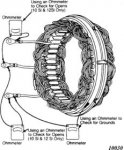
Mike, I realize I don't have the best explanations of how to do things or test things, but I have found a pictorial diagram about how to do a stator test that fits very well with your situation.

1193133778.gif

I hope this helps in understanding how to check for a good or verify a bad stator. While it is a standard setup for a GM alternator, it is the exact same procedures for testing most any stator. As you can see you use an OHM meter (on the X1 scale) to test between the individual wires to verify they are not opened and even if they read shorted, that is because the resistance is so very low they appear to be shorted to one another. Unless you have a micro-ohm meter, you probably won't be able to tell much about the actual low resistance. But it does verify an open coil wire(s). And you can also see how they test to ground (in this picture the coil frame) to verify it is not shorted to ground as well. Hope this makes better sense then my pitiful attempt at explaining...
 

V153

Lieutenant Commander
Joined
Apr 16, 2011
Messages
1,764
Resistance should be around 540 Ohms across the brown leads to the power pack(s).

Yellow leads to voltage regulator/rectifier should read under 2 Ohms.
 
Last edited:

Fed

Commander
Joined
Apr 1, 2010
Messages
2,457
Should have 2 wires coming out, Yellow & Yellow/Grey.
Expect the continuity test to be very low around the 1 ohm mark and should be very high to ground infinity.
You would need to find someone with a manual to get the right number.
FWIW my 1988 90HP 9Amp stater resistance value is 0.7 ohms.
 

V153

Lieutenant Commander
Joined
Apr 16, 2011
Messages
1,764
Correction. Per the manual.

Brown leads: 500 ohms plus or minus 50

Yellow leads: .7 ohms plus or minus .05
 
Top