Does this look like a schematic for a DVA --

jtexas

Fleet Admiral
Joined
Oct 13, 2003
Messages
8,646
this was suggested to me for measuring low peak voltage -
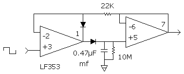
pk.gif


the LF353 is a dual op amp http://www.national.com/ds/LF/LF353.pdf

or this -
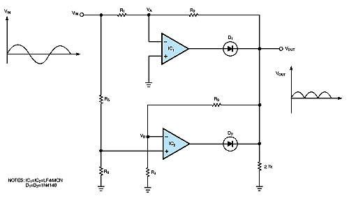
06di1fg1.gif


obviously you would need to add a capacitor

any comments?
 

bruceb58

Supreme Mariner
Joined
Mar 5, 2006
Messages
30,581
Re: Does this look like a schematic for a DVA --

They are just amplifier circuits that are also rectifying the signal coming in.

What are you trying to measure?

Can you borrow an oscilloscope? The reason I say this is that you are going to have no idea what Vout/Vin is going to be without testing the circuit first with known conditions. And if you have a scope, you might as well just use it!

By the way, what is a DVA?
 

jtexas

Fleet Admiral
Joined
Oct 13, 2003
Messages
8,646
Re: Does this look like a schematic for a DVA --

sorry, coulda been more specific..........I would like to be able to measure the peak AC voltage on the trigger wires from the stator of my'79 rude's CD ignition, which are said to be in spec if >= 0.5V peak AC. Is why a simple rectifier wouldn't work on account of the voltage drop across the diodes. DVA = direct voltage adapter for a multimeter, to measure peak AC (vs average or RMS). near as I can tell, only fluke & stephens makes 'em. I just thought it might be kinda fun to fabricate my own. I want to plug the outputs into my DMM, set on VDC, and probe the stator.

I'd also need to measure peak AC output from the powerpack to coils, at least 150V.

nope, I have no scope.
 

bruceb58

Supreme Mariner
Joined
Mar 5, 2006
Messages
30,581
Re: Does this look like a schematic for a DVA --

That first circuit won't work for you becuase the first amplifier has no gain and the diodes are going to drop you 0.7V.

I would think you would still need a scope to calibrate yourself becuase I don't think you would have any way of knowing if your circuit is working properly after you built it. I guess you could put in a DC voltage and calibrate it that way.
 

Bindernut

Seaman
Joined
Jul 12, 2006
Messages
63
Re: Does this look like a schematic for a DVA --

My op-amp theory is a bit rusty, but I believe that in circuit #1, the first op-amp is biased by the diode between pins 1&2 to compensate for the drop across the diode conecting the two amp stages. Should be a true zero-gain if the diodes are matched...will probably be off a wee bit due to tolerances though. The second stage op-amp is zero-gain. If I remember right (and I admit I'm rusty on amp circuits!), that circuit is used for a zero-to-positive peak input. If you're measuring -peak-to-+peak, I think it'll only look at the zero-to-positive side of the input , ignoring the neg-to-zero half of the waveform. Output will look like this... "/\/\/\/\/\" input wll get you a half-wave "^-^-^-^-^' output

With either circuit, if you put a cap on the output it'll average the half-wave or full-wave output and not give your a true peak level anyway.

I'm pretty positive you'd need a scope to at least check the calibration of the thing anyhoo. If you can borrow a scope to do the calibration, I would just use the scope to watch your CDi signal.

(Feel free to publicly flog me if I'm wrong...it's been a few years! And Bruceb's degree is bigger than mine!)
 

bruceb58

Supreme Mariner
Joined
Mar 5, 2006
Messages
30,581
Re: Does this look like a schematic for a DVA --

My suggestion is to go online somewhere and find a free SPICE model program and plug it into that and see what it does and to design something with the voltage levels that you want.

Really been awhile since I have done op-amp design but when you start using large resistors like the 1M and the 22K to set gain, everything gets thrown off by the input leakage currents.

I still say you should beg/borrow/steal a scope.
 

ricksrster

Commander
Joined
Jun 19, 2005
Messages
2,022
Re: Does this look like a schematic for a DVA --

Somebody awhile back had plans for a DVA. It looked like a bridge rectifier with a capacitor across it. I tried to do a search and couldn't find it.
 

bruceb58

Supreme Mariner
Joined
Mar 5, 2006
Messages
30,581
Re: Does this look like a schematic for a DVA --

He can't use a bridge rectifier because of the voltage drop across the diode.
 

jtexas

Fleet Admiral
Joined
Oct 13, 2003
Messages
8,646
Re: Does this look like a schematic for a DVA --

I hadn't thought about the calibration aspect - I bet somebody I know has a scope. I don't have a particular need for it right now, just thinking ahead.

And sure, anybody can pay $150, or $50, or $42, but where's the challenge in that?

A plain vanilla full wave bridge rectifier with a cap across the outputs should work fine for checking powerpack output.

And by the way pretty much anybody with an outboard built between about 1974 and 20xx might have a need for one sooner or later.
 
Top