Draw on battery 1

rickasbury

Master Chief Petty Officer
Joined
Jul 13, 2011
Messages
810
I have always had a battery issue. I did the following test on the system.
As far as checking, multimeter on 10 amp max setting. Ignition is off- battery switch is off. I have not rechecked battery 2 but it was dead 0 on the draw. The only thing I'm sure i should have done but did not was taking the genset off. Not sure why I think that but would make sense to rule it out. So, the test is remove the neg cable and test between the post and the cable.

The radio is dead and will not turn on. I do not know if the amp is on or not - 4 amps though?

Battery switch during test is off.

As far as other electrical issues-
The spot light is not operating. I thought the control head was bad and replaced it. It was going up and down but now it does nothing. I did not pull the two blade fuses but assume this is not going to be a draw.

No tv plugged in..radio off. No bilge pumps running. As mentioned the sump pump is bad or jammed up- i cut the wires to it.

I guess pulling fuses and find the circuit it is comming from?
 

ESGWheel

Ensign
Joined
Aug 29, 2015
Messages
903
I am having a difficult time following your story but will try to help. I assume you have a dual battery system with a Battery Switch that is 1, 2, Both or Off. Further that you are seeing a current draw on Batt 1 even though the switch if set to Off.
  • How are you are detecting that current draw on Batt 1?
If your Batt selector switch is not comprised (broken somehow) then there must be leads other than the heavy battery cable from the positive terminal to the Batt Switch. These smaller wire leads will be either connected directly to the Pos Terminal of Batt 1 or at the Batt 1 terminal at the switch. So, something like the bilge pump. Disconnect these wires one at a time and you will find your culprit.

To check the Batt Switch, disconnect all the leads to it (make sure you disconnect the other ends at the battery first!) and with the switch to Off check the resistance between the various terminals > should be open circuit.

Also, I do not know how your genset is tied into all this so above assumes it does not connected to the Batt Switch functions.

And a note of caution: you now have a disabled bilge pump (“the sump pump is bad or jammed up- I cut the wires to it”) and it seems as if you boat is always in the water. IMHO, getting that replaced / repaired is your first priority.
 

rickasbury

Master Chief Petty Officer
Joined
Jul 13, 2011
Messages
810
I am having a difficult time following your story but will try to help. I assume you have a dual battery system with a Battery Switch that is 1, 2, Both or Off. Further that you are seeing a current draw on Batt 1 even though the switch if set to Off.
  • How are you are detecting that current draw on Batt 1?
If your Batt selector switch is not comprised (broken somehow) then there must be leads other than the heavy battery cable from the positive terminal to the Batt Switch. These smaller wire leads will be either connected directly to the Pos Terminal of Batt 1 or at the Batt 1 terminal at the switch. So, something like the bilge pump. Disconnect these wires one at a time and you will find your culprit.

To check the Batt Switch, disconnect all the leads to it (make sure you disconnect the other ends at the battery first!) and with the switch to Off check the resistance between the various terminals > should be open circuit.

Also, I do not know how your genset is tied into all this so above assumes it does not connected to the Batt Switch functions.

And a note of caution: you now have a disabled bilge pump (“the sump pump is bad or jammed up- I cut the wires to it”) and it seems as if you boat is always in the water. IMHO, getting that replaced / repaired is your first priority.
Thank you sir for your reply! I'm sure you can detect I'm not a proficient electrical person - basic trouble shooting, checking relays I can do. This I understand is going to be hard for me to figure out.

You have my set up. Our boat is a 270 Rinker. I do have the two batteries with a battery selector switch. I'm the second owner, it had about 50 hours on it when I bought it (or that's what the hour meter said). I had to change out the guage at 320 so it's around that now. 2006 boat I've had for 10 years. It has shore power, a/c, hot water heater, shower with a sump pump, windless. It also has a Kohler genset, remote spot light. Mercathode system also (which I know zip about)

*How are you are detecting that current draw on Batt ?
I removed the negative terminal from each battery. Selector switch is off. I measured amps on my multimeter between the terminal end and the battery post. Bat 1 was like 3 to 4 amps (meter set on 10) . Bat 2 was dead 0 - if I'm checking this right.
I'm not aware of any damage to the selector switch itself. It turns smoothly so nothing obvious to me with the switch.
Yes, there are other wires connected to the batteries. I have lead/acid batteries that have the seperate terminals for accessories. Bat one, I believe has the pos/neg for the genset. Bat 2 has one connection to the negative terminal, nothing on the positive.
With regard to the bilge pump repair- it's not the bilge pump it is the sump for the shower. I noticed when I tested the shower it did not drain- so the box where the water runs into has the pump- the pump seems frozen up so I thought perhaps since the float was trying to start the pump it may be pulling power if it's wired to the same circuit as the bilge pumps. The box is located in a compartment in the midship bearth (aka storage area!) . There is a bilge pump there (2nd by the motor), a/c thruhull and filter.
I have never messed with that battery selector, it sounds pretty scary . I will start by pulling the 2 genset wires off first? If that does not work I'm going to pull out the selector. I was assuming everything that has a wire runs through that switch but I'm guessing this switch is a distribution center and there probably not as many wires as I fear! So if I'm looking at the back of the switch, the terminal that has that battery positive cable, there would be just a few wires on it to remove and keep testing? Once I find the offender I'm sure figuring out where it goes will be the fun part!
Thanks again for your reply- and sorry for my lengthy response but I wanted you to "know " the boat as best as I could describe.
 

ESGWheel

Ensign
Joined
Aug 29, 2015
Messages
903
excellent and helpful write up. i will respond more fully in abt an hr or less but wanted to say thanks for the additional detail....
 

ESGWheel

Ensign
Joined
Aug 29, 2015
Messages
903
Good to know I was confused about the sump pump.

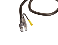
Your method of measuring the draw is perfect. BUT I assume there is ONLY the heavy negative battery cable attached to the battery post. No other wires or if there are, they are all tied into that battery cable. See picture below for what I mean. Either way the key is that your multimeter alone is completing the circuit between the battery cable (and any attached wires to it) and the battery post.

Now another question: are you seeing current being drawn off the battery (i.e. discharging?) or is it possible you are seeing your shore power onboard charger actually charging the battery? Please understand I need to ask this.

Let’s assume you are disconnected from shore power, GenSet is off and you are indeed seeing the battery discharging at that 3 to 4 AMP rate.

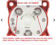
Thus set up the current measuring on Batt 1 again. Now disconnect (one at a time) any of the smaller wires (not the large battery cable) attached to the Batt Pos Post or the Switch Pos Post (the wires can be at either location as it’s the same electrically > see other picture).

When the current drops to zero you found the device doing the draw. If still have a draw (i.e. disconnecting the smaller wires made no difference) then pull the battery cable itself.

Post results as I believe there are two basic directions this will lead to depending on when the current drops to zero: (1) an accessory device or something like the Genset (the smaller wires) or (2) something going on with the engines electrical (the battery cable).

More: if there is something going on with the boats wiring, like an issue with the Genset then it will be best to get a marine certified electrician involved. Right now we are doing basic troubleshooting in hopes this is something easy and simple to identify and fix. Said differently, boats with Gensets and Shore Power have particular needs and if set up / repaired incorrectly can lead to fires and / or electrocution.
 

Attachments

  • Neg Batt Cable with Lead.png
    Neg Batt Cable with Lead.png
    61.7 KB · Views: 1
  • Back side of switch.png
    Back side of switch.png
    519 KB · Views: 1

rickasbury

Master Chief Petty Officer
Joined
Jul 13, 2011
Messages
810
This is a 270 of a friend of mine and would have to assume would reflect mine also. I don't think anything was added to the boat other than factory. It does have an amp i do not know what the power source is.
Thanks!
 

ESGWheel

Ensign
Joined
Aug 29, 2015
Messages
903
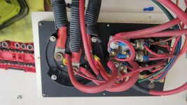
That looks like the back of the selector switch. Is that correct?
  • If yes, then that is what I was talking about > leads (wires) coming off of it directly from the battery and not switched.
Be careful taking off those ‘smaller wires’ one by one on the back of the Switch. Here is my suggestion:
  1. First find out which of the main switch terminals are for Batt1 and Batt2. Here is how > Switch to Off and everything thing else off (no shore pwr, no genset). Using your multimeter (MM) check for +12VDC on all the three lugs. 2 of them should be +12V, other not (that is the output terminal). Disconnect Batt2 from its battery cable at the battery. Test again for +12VDC. The lug with +12V is Batt 1. Remember or mark it.
  2. Now disconnect Batt 1 battery cable from the post of Battery 1. This is a safety issue to preclude arcs and sparks. At the Switch remove the lug nut for Batt 1. Restack the wires onto the post such that the heavy battery cable is on first followed by next biggest, etc., until all the wires are back on the lug in a biggest to smallest arrangement. Put the nut back on and tighten more than finger tight. Note Batt 2 is still disconnected and will remain so.
  3. Now set up your current detector with the MM on the Neg side of Batt1.
  4. Attach the Batt1 cable back onto the battery post. Verify you are getting that 3 to 4 amps of draw.
  5. Remove the Batt1 post cable off the battery post. Remove the nut off the switch post and pull off the first wire making sure it does not come into contract with anything. Reattach the Batt1 cable back onto the battery post. Check MM for current draw.
  6. If current draw repeat above but pulling off the next wire off the switch post (do not reinstall and already pulled off wire > you are step by step stripping that post of its wires). Continue to repeat until no current draw.
When no current draw, that wire just pulled off is the issue. What does it go to?
 

rickasbury

Master Chief Petty Officer
Joined
Jul 13, 2011
Messages
810
That looks like the back of the selector switch. Is that correct?
  • If yes, then that is what I was talking about > leads (wires) coming off of it directly from the battery and not switched.
Be careful taking off those ‘smaller wires’ one by one on the back of the Switch. Here is my suggestion:
  1. First find out which of the main switch terminals are for Batt1 and Batt2. Here is how > Switch to Off and everything thing else off (no shore pwr, no genset). Using your multimeter (MM) check for +12VDC on all the three lugs. 2 of them should be +12V, other not (that is the output terminal). Disconnect Batt2 from its battery cable at the battery. Test again for +12VDC. The lug with +12V is Batt 1. Remember or mark it.
  2. Now disconnect Batt 1 battery cable from the post of Battery 1. This is a safety issue to preclude arcs and sparks. At the Switch remove the lug nut for Batt 1. Restack the wires onto the post such that the heavy battery cable is on first followed by next biggest, etc., until all the wires are back on the lug in a biggest to smallest arrangement. Put the nut back on and tighten more than finger tight. Note Batt 2 is still disconnected and will remain so.
  3. Now set up your current detector with the MM on the Neg side of Batt1.
  4. Attach the Batt1 cable back onto the battery post. Verify you are getting that 3 to 4 amps of draw.
  5. Remove the Batt1 post cable off the battery post. Remove the nut off the switch post and pull off the first wire making sure it does not come into contract with anything. Reattach the Batt1 cable back onto the battery post. Check MM for current draw.
  6. If current draw repeat above but pulling off the next wire off the switch post (do not reinstall and already pulled off wire > you are step by step stripping that post of its wires). Continue to repeat until no current draw.
When no current draw, that wire just pulled off is the issue. What does it go to?
Thanks for the detailed trouble shooting-one thing I want to clarify, especially if someone else will be following this later.
If I'm doing it correctly, checking for the amp draw is with the cable disconnected, mm on 10 amps and checking between the neg cable and the neg bat because that's where amps travel?!
This has been an issue since I've owned it. I hope you stick around to help me find where that wire goes!
 

ESGWheel

Ensign
Joined
Aug 29, 2015
Messages
903
My philosophy on posting is to only post where I think I can contribute or help. And if I am trying to help an Original Poster (OP) then I stay with it to the end or at least as far as my knowledge. In my experience its usually the OP who will stop posting (prior to resolution). So yes, I will stick with you with the understanding that I am not a certified marine electrician and if we are treading into an area where I think one is needed, I will highlight that and stop. This is because safety is paramount, especially in a boat and I not only preach it, I practice it. It is the reason I highlighted about your priorities when I thought you had a non-functioning bilge pump. But enough about me :)

Yes, you are hooking up the MM correctly based on your description. However, here is an article that goes into it with photos (link) to remove any doubt / help others. Note: his hand drawn diagram show the Black (common) lead going to the mA versus the COM on the MM, a mistake. His pictures of the actual MM are correct.

And yes, you need a complete circuit for the “amps to flow”. In other words, any current (amps) flowing out of the Positive Post of the battery also will be flowing into the Negative Post of the battery completing the circuit.
 

rickasbury

Master Chief Petty Officer
Joined
Jul 13, 2011
Messages
810
My philosophy on posting is to only post where I think I can contribute or help. And if I am trying to help an Original Poster (OP) then I stay with it to the end or at least as far as my knowledge. In my experience its usually the OP who will stop posting (prior to resolution). So yes, I will stick with you with the understanding that I am not a certified marine electrician and if we are treading into an area where I think one is needed, I will highlight that and stop. This is because safety is paramount, especially in a boat and I not only preach it, I practice it. It is the reason I highlighted about your priorities when I thought you had a non-functioning bilge pump. But enough about me :)

Yes, you are hooking up the MM correctly based on your description. However, here is an article that goes into it with photos (link) to remove any doubt / help others. Note: his hand drawn diagram show the Black (common) lead going to the mA versus the COM on the MM, a mistake. His pictures of the actual MM are correct.

And yes, you need a complete circuit for the “amps to flow”. In other words, any current (amps) flowing out of the Positive Post of the battery also will be flowing into the Negative Post of the battery completing the circuit.
One more thought...is my offending device possibly in a circuit so that if I pulled fuses rather than wires I might track it down and little quicker? I have seen some standards on wire colors used for specific purposes...but not sure that would be conclusive? Trying to follow wiring seems like a nightmare- it has miles of it.
 

ESGWheel

Ensign
Joined
Aug 29, 2015
Messages
903
You can try it, but I assume you are talking about a fuse panel which I suspect would be fed with +12VDC only when the selector switch is “on” (1, 2 or both). If you can probe the fuse panel with your MM with the Switch in Off (and no shore power and no genset) and its hot (ie shows +12VDC) then yes, by all means.

Regarding tracking wires: any wire directly connected to the battery should be a ‘critical system’ like a bilge pump. So, the number of devices it could be are extremely limited and should be easily identifiable without having to physically trace the wire to the device. However they do make a cheap tracer like this link, where you would put that tone generator on the wire and then go to devices to see if get a tone.

You mentioned an “amp” which I assume is for the sound system. These can draw a LOT of power and are typically wired directly to the battery (or the back of the selector switch). One method by which these amps work is they do not “turn on” until they get a signal from the stereo. Perhaps your amp is not working correctly and has a constant draw.

More on this: you mentioned this current draw has existed since you bought the boat some 10 years ago. How have you been managing that? Did you discover this draw by constantly dealing with a dead battery? Are you removing Batt1 cable off its post when you dock the boat to keep it from going dead? Must be frustrating.
 

dingbat

Supreme Mariner
Joined
Nov 20, 2001
Messages
16,808
Anything involving a stator and or rotor is subject to current/ground leakage.
Generators and electric motors (bilge, starter) are the prime suspects until proven otherwise.

The first thing I'd do is to remove all wiring from the batteries with the exception of the battery cables and disconnect the generator from the system.
 

rickasbury

Master Chief Petty Officer
Joined
Jul 13, 2011
Messages
810
You can try it, but I assume you are talking about a fuse panel which I suspect would be fed with +12VDC only when the selector switch is “on” (1, 2 or both). If you can probe the fuse panel with your MM with the Switch in Off (and no shore power and no genset) and its hot (ie shows +12VDC) then yes, by all means.

Regarding tracking wires: any wire directly connected to the battery should be a ‘critical system’ like a bilge pump. So, the number of devices it could be are extremely limited and should be easily identifiable without having to physically trace the wire to the device. However they do make a cheap tracer like this link, where you would put that tone generator on the wire and then go to devices to see if get a tone.

You mentioned an “amp” which I assume is for the sound system. These can draw a LOT of power and are typically wired directly to the battery (or the back of the selector switch). One method by which these amps work is they do not “turn on” until they get a signal from the stereo. Perhaps your amp is not working correctly and has a constant draw.

More on this: you mentioned this current draw has existed since you bought the boat some 10 years ago. How have you been managing that? Did you discover this draw by constantly dealing with a dead battery? Are you removing Batt1 cable off its post when you dock the boat to keep it from going dead? Must be frustrating.
Yes, it has been frustrating. As long as I was bringing it home and keeping it charged I managed to get by a bit- the auto parts store was getting pretty tired of seeing me. I should have been disconecting both of the batteries until I got this far- I had various other "priority " items like pulling the motor and rebuilding the merc transom...it's been a bit of a love hate relationship...I've boated a very small area but would like to feel safe in venturing out a little further.
As far as the fuse panel, I was talking about removing each fuse as I check the draw. I do need to retest with the genset removed. There are a couple higher amp fuses at the selector switch and then at the helm there are probably 20 or so. I can remove each fuse just like removing each wire?
Everything is on that battery switch- as mentioned the genset wires are on bat one and then one neg wire on bat two. I don't think the pos cables have any other wires built into those.
I am suspecious of that amp - the boat bag has brochures and owners manuals and look like they were either showroom materials or factory books so I'd think it was installed by rinker? Maybe the dealer does it and they just wired it however...I need to see if I can unplug that from the system and test too- it would be really sweet to figure this out.
 

Jeff J

Petty Officer 1st Class
Joined
Jun 23, 2021
Messages
369
I am being lazy today so haven’t read everything posted in this thread. Apologies if I am duplicating someone.

3 things that seem to be commonly wired directly to a battery that can drain it are the radio memory (radio won’t work but must have constant power to keep time and/or save settings), automatic bilge pumps and electric assisted steering pumps.

The radio takes a while to drain a battery. Usually 30 days or so. Bilge pumps can drain pretty quickly but have to be on. I have seen a few stick on and burn out in a dry bilge. The electric assisted steering pumps can drain a battery in a week or so just sitting on a lift.
 

ESGWheel

Ensign
Joined
Aug 29, 2015
Messages
903
Yes you can do that. But a polite reminder that most items are not connected directly to the battery, so unsure of the utility. If there is concern about manipulating the Batt Switch (unmounting it, getting to the backside) do not be overly so. It’s a robust device and does not ‘come apart’ by simply dismounting it. Just need to be careful about grounding out any of the wires on the backside > in other words you pull it off its bulkhead and inadvertently touch one of the posts on the back to metal / ground. To remove this risk, disconnect both Pos cables from both batteries. You will find that turning it over may be a little tough fighting the thick wires, but once in position and all good, connect back up Batt1 and check to see which Switch post is hot and then follow the process above. So start easy (fuses) and hopefully that will highlight the issue. But if not.... :)

Good luck and keep posting, you will get there!
 

rickasbury

Master Chief Petty Officer
Joined
Jul 13, 2011
Messages
810
Yes you can do that. But a polite reminder that most items are not connected directly to the battery, so unsure of the utility. If there is concern about manipulating the Batt Switch (unmounting it, getting to the backside) do not be overly so. It’s a robust device and does not ‘come apart’ by simply dismounting it. Just need to be careful about grounding out any of the wires on the backside > in other words you pull it off its bulkhead and inadvertently touch one of the posts on the back to metal / ground. To remove this risk, disconnect both Pos cables from both batteries. You will find that turning it over may be a little tough fighting the thick wires, but once in position and all good, connect back up Batt1 and check to see which Switch post is hot and then follow the process above. So start easy (fuses) and hopefully that will highlight the issue. But if not.... :)

Good luck and keep posting, you will get there!
Thanks- i will get back to this!
 
Top