Evinrude Carborator Rebuild 50HP/1989

Status
Not open for further replies.

Otte

Petty Officer 1st Class
Joined
Jul 26, 2011
Messages
273
Please let me know if there is a more detailed explanation of how to re-do the carburetors for a 1989 50HP Evinrude. I have a Sealoc repair manual for my engine but it lacks the detail I need to remove the throttle links.
1. I have the carburetor kit with float from iboats.
2. I have removed the air silencer front and back off the carbs.

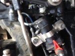
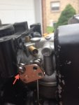
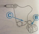
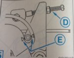
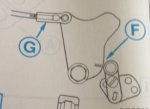
Now I have to get the nuts off the carbs in order to remove them from the engine block but the throttle links are in the way of removal. How do I do this? Thanks for any help you folks can give me. I hope this photobucket thing works.

<iframe src="http://s900.photobucket.com/user/Bret_Otte/story/40047/embed" width="650" height="400" frameborder="0" scrolling="no"></iframe>
 

racerone

Supreme Mariner
Joined
Dec 28, 2013
Messages
38,454
Can you turn those linkages out of the way with your fingers ?------Just give that a try.
 

Otte

Petty Officer 1st Class
Joined
Jul 26, 2011
Messages
273
No Title

After reading your suggestion I just went out and tried that now with a wrench but I butt up against the linkage. It looks as though I have to disengage the link to get at the nuts behind. I just want to make sure I am not creating more work for myself later if I do something that has an easier solution. Do I have to tap those small pins out to disconnect the link and pull them through the carb?
 

racerone

Supreme Mariner
Joined
Dec 28, 2013
Messages
38,454
Sorry but you are making this difficult for yourself and for no reason at all !!!
 

Otte

Petty Officer 1st Class
Joined
Jul 26, 2011
Messages
273
No Title

??? Not sure how to respond your post racerone other than I suppose I am but I don't know how to proceed in taking off the carbs if I can't get a wrench behind the linkage to loosen up the nuts to remove the carbs from the engine.
 

Otte

Petty Officer 1st Class
Joined
Jul 26, 2011
Messages
273
I got them off... so it was not that tough but the linkage arm needed to be popped out of the plastic seat and the throttle/gear link had to be removed. Moving those two items allowed me to slowly turn off the 1/2 inch nuts holding the carbs on to the engine block. It was a slow process but by loosening the nuts equally on each side of the carb I could wiggle the carb out and unscrew each nut further.
 

Otte

Petty Officer 1st Class
Joined
Jul 26, 2011
Messages
273
No Title

What is behind these plugs? How important is the carb re-build that these come out and cleaning happens behind them?
 
Last edited:

ronward

Petty Officer 1st Class
Joined
Jun 24, 2013
Messages
346
If the passages under those plugs are dirty then it is a must do. If they aren't dirty then it's not that critical. But you can't know unless you remove them. It's easy to do and since you are already going this far then why not do it. Use a small drill bit to just barely get through the plug. Be very careful to not let the drill slam through and bottom out under the plug, you will damage the small passages underneath. Put a nail or screw in the hole and pry out the plug. Use a small diameter wire to clean the holes. Be sure to use plenty of spray carb cleaner and compressed air to get everything cleaned and blown out. Good idea to wear safety glasses because it's hard to tell what hole that cleaner and air is going to come out of, you won't like that carb cleaner in your eyes. When you put the plug/or plugs back in use a hammer and punch to gently flatten them a little to seal them. Be careful you don't flatten them too much. To be on the safe side I then put a couple drops of super glue around the top to make sure they don't leak.
 

Otte

Petty Officer 1st Class
Joined
Jul 26, 2011
Messages
273
Got it... Thanks ronward. I was having a tough time finding info on how to remove the plugs.
 

Otte

Petty Officer 1st Class
Joined
Jul 26, 2011
Messages
273
Got it... Thanks ronward. I was having a tough time finding info on how to remove the plugs.
 

Davee3

Seaman Apprentice
Joined
May 26, 2013
Messages
40
Guess this is my next step too 3 tries without removing the plugs - Although now sitting in Sea Foam I see some black specs that did not come out on 3 tries

Will leave sitting & try again tomorrow b4 removing the plugs Super glue great idea I thought I needed new ones
 

Otte

Petty Officer 1st Class
Joined
Jul 26, 2011
Messages
273
No Title

Carbs are done. Running great at WOT but had a tough time running at idle. I adjusted the screw under the flywheel on the port side of the engine and that seemed to help. More experimentation needed on the water for that one.

Now I seem to have a slight "lug" or "engine nodding" when I have been running close to WOT for about 30-40 min. When I back off the throttle, yet still in a plane, it sorts out and I have not further problems. The engine also starts a bit rough even when warm. So I checked the primer solenoid.
1. I disconnected the solenoid wires but left the fuel lines on the solenoid.
2. When I checked the primer solenoid and did not fall within specs of 4-7 ohms.
2a. I have the Cen-Tech Mulit-Meter on the 200 ohms setting and connected the red lead of the Multi-meter on the purple/white stripe of the primer and the black lead of the meter connected to to the black ground of the primer.
2b. The numbers on my Cen-Tech Multi-meter were going all over the place as you can gather from the pictures. The readings settled down for a short time in the high teens to low 20s.

I want to make sure with you folks that I have set up my diagnostics correctly and and I am not going to replace a part that is not broken. I included the pictures so you can see how the primer was set up before I disconnected it from the engine and to see some of what I am experiencing.

So what do you think? Did I set this primer diagnostic up correctly? Is it time for a new primer solenoid? I did not fine a new primer on iboats but found another for $160.00... ouch. What else could be causing this near WOT issue?
 

Otte

Petty Officer 1st Class
Joined
Jul 26, 2011
Messages
273
No Title

Pictures for previous post.
 

Attachments

  • photo202816.JPG
    photo202816.JPG
    40.8 KB · Views: 2
  • photo202817.JPG
    photo202817.JPG
    37.1 KB · Views: 2
  • photo202818.JPG
    photo202818.JPG
    36.1 KB · Views: 1

Otte

Petty Officer 1st Class
Joined
Jul 26, 2011
Messages
273
Went back out and tested the primer solenoid twice today. Temperatures were cooler and, after a little jumping around, got two separate readings of 8.5. Any ideas on what to check next? I should change the name of this thread to... something else.
 

jakedaawg

Rear Admiral
Joined
Jun 26, 2012
Messages
4,275
check primer solenoid resistance with engine off and solenoid isolated. Check volatage to solenoid.

to check resistance with engine off simply unhook the purple and black wires. do ohms check between purple and black wires that come from solenoid.

Usually you will find the solenoid is good and key switch is bad. you determine this by placing a voltmeter between the purple and bkack leads on the engine side with the engine running. without the key pushed in you should have less than .2V, with the key pushed in you should have 12+V. you are in the posssible trouble range if you have more than 4V or so without the key pushed in. If bad replace key switch, they do not last forever.
 

Otte

Petty Officer 1st Class
Joined
Jul 26, 2011
Messages
273
Thanks daawg - Your first point is exactly how I checked the primer solenoid and it seems to check out well. I will check the starter switch tomorrow. Did you mean to type .2V or 2V without the key pushed in?

I just ordered a Johnson/Evinrude Service Manual for 1989 40-50 horse and an OMC parts Manual for 1989 25/40/50 horse outboards off Flea-Bay tonight. Total came to 44.50. My Seloc book has done right by me but now I am getting in to specific readings and need some more help.
 

Otte

Petty Officer 1st Class
Joined
Jul 26, 2011
Messages
273
No Title

Okay - Between working on lower unit seals and finishing the carbs... I have been busy and greasy. Primer has checked out okay. Before I went and messed with the remote starter I decided to back up and check the fuel linkages. Turns out between the previous owner and myself, to get the engine running okay with bad carbs, we had the links pretty messed up. So here is the OEM process for anyone else working on a 1989 40, 48 and 50 models from the same year.
Preliminary Adjustments
1. Remove the throttle cable from throttle lever 'A'.
2. Measure and, if needed, adjust the length of throttle control rod 'B'. It should be approximately 7 13/16 in. to the center of the socket.
3. Measure and, if needed, adjust the length of the spark control rod 'C'. It should be approximately 2 1/16 inches, measure between the centers of the two sockets.
- The sockets were tough for me to separate. I had to use more force than I thought or was comfortable with on the throttle control rod. I did not have to mess with the spark control rod. I used a pliers to squeeze the socket back in place... yikes.
4. Loosen the cam follower adjustment screw 'D' and move the cam follower away from the throttle cam.
5. Adjust the idle speed screw 'E' until the spark lever cam follower is between the alignment marks 'F'. Then tighten the idle speed screw locknut.
- Okay here is were I was stumped for a bit. I could not get the spark over cam to line up between the arrows. Turns out I had to adjust the throttle control arm to make that happen. Nothing in the OEM service manual about that one.
 

Otte

Petty Officer 1st Class
Joined
Jul 26, 2011
Messages
273
No Title

Throttle Plate Synch.
1. Loosen carburetor lever adjustment screw on upper carb.
2. Rotate both throttle shafts slightly and allow them to snap shut.
3. Press up gently on the adjusting tap and tighten the upper carb adjustment screw.
4. Verity that both throttle shafts begin to rotate at exactly the same time.
 

Attachments

  • photo203656.JPG
    photo203656.JPG
    24.7 KB · Views: 0

Otte

Petty Officer 1st Class
Joined
Jul 26, 2011
Messages
273
No Title

Cam Pickup Point
1. Move the throttle cam and cam follower toward each other. Picture #1
2. Tighten the cam follower adjustment screw 'B' when the cam and cam follower are just touching at the pickup mark 'C'. When doing this step, the carb throttle plates must be closed and the pickup mark 'C' must point at the center of the cam follower. Picture #1
3. Push idle speed screw 'D' against its stop and verify that spark lever cam follower is between alignment marks 'E'. Picture #2
4. With the idle speed screw against its stop, verify that there is a 0.010 inch or 0.25 mm gap 'F' between the throttle cam and cam follower. If the 0.010 inch gap is not there then adjust the throttle control rod socket 'G' to achieve the gap 'F'. Picture #3
 

Attachments

  • photo203660.JPG
    photo203660.JPG
    29.5 KB · Views: 2
  • photo203661.JPG
    photo203661.JPG
    33.9 KB · Views: 2
  • photo203662.JPG
    photo203662.JPG
    27.3 KB · Views: 2
Last edited:
Status
Not open for further replies.
Top