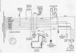
Well, i am attempting to get my head around the wiring diagrams for our boat. The power is twin Merc 255MIE's Pre BIA code. Here is my questions:
1. Why does positive hook up to the negative and the positive terminals on the ammeter? can power pass through between the points?
2. where do the 2 wires in the diagram that are shown comming off the bottom of the alternator actually connect?
3. What do the B, A, C, and I stand for on the ignition switch? which one is what?
4. How do i tell which terminal is R and which is S on a non mercruiser starter?
5. How does the engine kill with these diagrams, it seems that the coil is hardwired to the battery and alternator, meaning it would be impossible to kill the engine?
6. What is the RESISTANCE CABLE? how is it different from a normal wire?
Thats all for now, any help would be appreciated