Gas gauge not working

MRS

Commander
Joined
Jul 10, 2005
Messages
2,579
I took pontoon out yesterday and gas gauge and nav lights not working plus the horn. They all worked last time out checked fuses and all the connections every thing
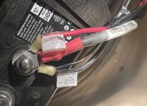
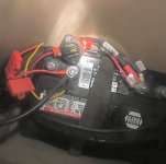
looks good. But did find this in the wire setup going to the gauge what is it and how do I test it? IMG_2098.jpg
 

dwco5051

Commander
Joined
Sep 14, 2008
Messages
2,452
That part is a buzzer which would be part of an audio alarm system which would sound on engine overheat or something similar depending on what motor. I don't think that in itself is causing your problem but surely would justify a good look behind the panel to find out why it fell out and what else may not be connected.
 

dwco5051

Commander
Joined
Sep 14, 2008
Messages
2,452
Reread your post and I am assuming you removed it and it didn't fall out. It may somehow be a buzzer to signal low fuel. I still don't think it is the cause of your trouble but without a wiring diagram I am not positive.
How to test it;
1) Connect it directly to 12v. If it buzzes it is a working buzzer.

2) Connect it to 12v. If it doesn't buzz it is a broken buzzer.

3) Connect it to 12v. If it blows up, spews fire and shrapnel causing temporary blindness and hearing loss it was something else that looks just like a buzzer.
 

MRS

Commander
Joined
Jul 10, 2005
Messages
2,579
That makes sense I never had a boat with a buzzer on it goes off when I turn the key on. It did not fall off I took off to get a good photo of it I had the starting battery go out so replaced it then I noticed fuel gauge and nav lights plus radio not working. RPM gauge trim gauge work plus can raise and lower O.B. those all work off the starting battery I have separate batteries for trolling motor and fish finder equip they all worked great.
 

dwco5051

Commander
Joined
Sep 14, 2008
Messages
2,452
That makes sense I never had a boat with a buzzer on it goes off when I turn the key on. It did not fall off I took off to get a good photo of it I had the starting battery go out so replaced it then I noticed fuel gauge and nav lights plus radio not working. RPM gauge trim gauge work plus can raise and lower O.B. those all work off the starting battery I have separate batteries for trolling motor and fish finder equip they all worked great.
Check the connections on the battery. It looks like the motor electrical is ok but the accessory circuit is not. If this trouble just started after changing the battery look and be sure all the smaller wires were reconnected and there is one hanging loose that my have been missed. Fuel gauge power would normally come from the accessory terminal on the ignition. Nav lights would not be on the same circuit. Makes be think a possible hot or ground missing from the battery.
 

MRS

Commander
Joined
Jul 10, 2005
Messages
2,579
Check the connections on the battery. It looks like the motor electrical is ok but the accessory circuit is not. If this trouble just started after changing the battery look and be sure all the smaller wires were reconnected and there is one hanging loose that my have been missed. Fuel gauge power would normally come from the accessory terminal on the ignition. Nav lights would not be on the same circuit. Makes be think a possible hot or ground missing from the battery.
Thank you going out now to check everything out.
 

MRS

Commander
Joined
Jul 10, 2005
Messages
2,579
I wonder if it could be the circuit breaker it did not pop but everything else looks good?
IMG_2099.jpeg
 

dwco5051

Commander
Joined
Sep 14, 2008
Messages
2,452
Normally black goes on negative, red on positive. The yellow and red are on the negative in the picture. They both have fuse holders on them which is normal for positive feeds. The wire feeding the circuit breaker I think is right if it is red and hidden behind the terminal cover in the picture. Does your boat have a radio/stereo? Usual wiring for them is yellow to constantly feed power so they don't lose pre-sets and red for off/on. Are you sure you put them all back on the same terminals that were on the old battery. What I believe you may now have is a couple of wires reversed. Don't take my word for it but trace them to be certain.
 

04fxdwgi25

Chief Petty Officer
Joined
Mar 25, 2022
Messages
583
Normally black goes on negative, red on positive. The yellow and red are on the negative in the picture. They both have fuse holders on them which is normal for positive feeds. The wire feeding the circuit breaker I think is right if it is red and hidden behind the terminal cover in the picture. Does your boat have a radio/stereo? Usual wiring for them is yellow to constantly feed power so they don't lose pre-sets and red for off/on. Are you sure you put them all back on the same terminals that were on the old battery. What I believe you may now have is a couple of wires reversed. Don't take my word for it but trace them to be certain.
Yup, fused circuits go to the + (positive) terminal, not the - (ground).
 

MRS

Commander
Joined
Jul 10, 2005
Messages
2,579
Thanks guys I am at work now will try when I get home never said I was the roundies marble in the bin🤓
 

dwco5051

Commander
Joined
Sep 14, 2008
Messages
2,452
Can you send a picture of the wires on the positive side or describe the ones hidden behind the terminal cover. There appears to be a black wire with a white tracer there and need a little more info on it. Is it part of a pair of one black and one black/white tracer? I wonder because some devices use that combo where black is neg and blk/wh is pos.
 

MRS

Commander
Joined
Jul 10, 2005
Messages
2,579
Can you send a picture of the wires on the positive side or describe the ones hidden behind the terminal cover. There appears to be a black wire with a white tracer there and need a little more info on it. Is it part of a pair of one black and one black/white tracer? I wonder because some devices use that combo where black is neg and blk/wh is pos.
 

Attachments

  • IMG_2100.jpeg
    IMG_2100.jpeg
    1.7 MB · Views: 7
  • IMG_2101.jpeg
    IMG_2101.jpeg
    1.7 MB · Views: 7

dwco5051

Commander
Joined
Sep 14, 2008
Messages
2,452
That is not b/w wire, just the reflection from the flash. The fix is simple. Move the red and yellow to the positive. The black to the negative. The motor wires are correct.
 

MRS

Commander
Joined
Jul 10, 2005
Messages
2,579
That is not b/w wire, just the reflection from the flash. The fix is simple. Move the red and yellow to the positive. The black to the negative. The motor wires are correct.
Thanks will try it this weekend and reply back Thanks again.
 

MRS

Commander
Joined
Jul 10, 2005
Messages
2,579
That is not b/w wire, just the reflection from the flash. The fix is simple. Move the red and yellow to the positive. The black to the negative. The motor wires are correct.
I did look at the black wires again they do have a white line on them will this make a difference?
IMG_2099.jpeg
 

04fxdwgi25

Chief Petty Officer
Joined
Mar 25, 2022
Messages
583
Looks like that black / white is in the same solderless connector termination as the one that labeled B+, so I would believe that is correct, if the terminations weren't recently redone.

Even if the breaker didn't "pop", check that you have B+ coming out the other side of it. Breakers being FUBAR are not uncommon. A simple test light is worth it's weight in gold in this troubleshooting situation.
 

dwco5051

Commander
Joined
Sep 14, 2008
Messages
2,452
I did look at the black wires again they do have a white line on them will this make a difference?
View attachment 404725
Got my curiosity up about the black/white tracer and after a little research did find that parallel grounds (what ever they are) will be marked that way. The heavy wires for the motor circuit are right as the red tape on the wire indicates. The red feed to the circuit breaker is right. the fused red and yellow which I am assuming goes to a radio/stereo should be positive. The only thing left is the two black/w wires in one crimp connector which would be negative/ground.
 

MRS

Commander
Joined
Jul 10, 2005
Messages
2,579
Got my curiosity up about the black/white tracer and after a little research did find that parallel grounds (what ever they are) will be marked that way. The heavy wires for the motor circuit are right as the red tape on the wire indicates. The red feed to the circuit breaker is right. the fused red and yellow which I am assuming goes to a radio/stereo should be positive. The only thing left is the two black/w wires in one crimp connector which would be negative/ground.
Got it thanks will swap everything this weekend thank you both.
 

MRS

Commander
Joined
Jul 10, 2005
Messages
2,579
Everything working but the fuel gauge might need to start the motor but didn’t have a water hookup ready. Thank you both you were spot on I should’ve taken a photo before disconnected cables I always do but not this time 🙄
IMG_2103.jpegIMG_2104.jpeg
 

dwco5051

Commander
Joined
Sep 14, 2008
Messages
2,452
Great. I once spent hours looking for a bilge pump problem on a bass boat a few years back because I set the battery on top of one of the ground leads and could not see it. BTW you did hook the buzzer back up?
 
Top