Hydraulic Pump Wiring (black wire floating free)

MaxGlide

Petty Officer 2nd Class
Joined
Aug 20, 2020
Messages
193
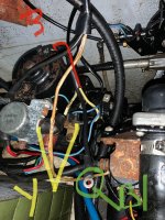
I have a 1977 Mercruiser and, what I think, is a single solenoid, hydraulic pump.

There are three wires coming off the pump, two yellows and one black, as seen in the photo. The two yellows are connected but the black is floating free.

While trying to reach the grease nipple for the steering mechanism, I must have created a live connection because this black wire started sparking like crazy. There is no spark when I manually ground it. During the sparking, the long, orange/yellow wire (centre-left of frame, going top to bottom, heated up like crazy.) This long, orangy/yellow wire is the power for the blower. I must have asked power there. (blower works fine)

Anyway, everything thing seems to be working fine. Motor starts, leg goes up and down, etc... I just have this black wire floating in space.

The only thing that is maybe odd is that the trim switch has one position where nothing happens. The switch has an UP button, an UP/OUT button and an IN button. IN works, UP/OUT with UP works and UP/OUT alone does nothing.

Sooooo.... where does this black wire go?!

Thanks for any input.
 

Attachments

  • IMG_7166.jpeg
    IMG_7166.jpeg
    1 MB · Views: 15
  • Screen Shot 2021-06-06 at 11.33.22 AM.png
    Screen Shot 2021-06-06 at 11.33.22 AM.png
    480.6 KB · Views: 13

shiloh87

Seaman
Joined
May 9, 2021
Messages
65
Attach that ground(blk) wire to the pumps mounting frame or any where you have a good grounding point.
In button is leg down, up is up for trim up to limit, both ups together to raise the leg for trailering, at least that`s how it works for my boat.
 

GA_Boater

Honorary Moderator Emeritus
Joined
May 24, 2011
Messages
49,038
No idea where the black wire goes.

Hold the Up and Up/Out at the same time to lift the outdrive to the trailer position.
 

MaxGlide

Petty Officer 2nd Class
Joined
Aug 20, 2020
Messages
193
Attach that ground(blk) wire to the pumps mounting frame or any where you have a good grounding point.
In button is leg down, up is up for trim up to limit, both ups together to raise the leg for trailering, at least that`s how it works for my boat.
I figured it had to be a ground because 1) it’s so shirt it in reaches screws that could be a ground 2) In diagrams the black is ground. What got me confused was the arcing of that wire, I must made contact somewhere. Also can’t figure out why UP/OUT button does nothing. Trailer function works with two buttons. 🤷🏻‍♂️
 
Joined
Mar 27, 2010
Messages
3,008
Here is a wiring diagram for Power Trim Circuit using a Single Solenoid.
 

Attachments

  • Single solenoid trim wiring.jpg
    Single solenoid trim wiring.jpg
    46.1 KB · Views: 14

GA_Boater

Honorary Moderator Emeritus
Joined
May 24, 2011
Messages
49,038
I may not have understood your remark about the Up/Out button. If you use the In button to completely lower the drive, will it raise with the Up/Out button? If no, check the Trim Limit switch.
 

MaxGlide

Petty Officer 2nd Class
Joined
Aug 20, 2020
Messages
193
I may not have understood your remark about the Up/Out button. If you use the In button to completely lower the drive, will it raise with the Up/Out button? If no, check the Trim Limit switch.
Here is how I understand the trim should work. IN button lowers leg all the way down. UP/OUT will only raise leg to a limited height. UP and UP/OUT buttons are pressed simultaneously to raise leg to trailering position. My setup works as such EXCEPT the pressing of only the UP/OUT button does nothing.
 

Bondo

Moderator
Staff member
Joined
Apr 17, 2002
Messages
71,088
Here is how I understand the trim should work. IN button lowers leg all the way down. UP/OUT will only raise leg to a limited height. UP and UP/OUT buttons are pressed simultaneously to raise leg to trailering position. My setup works as such EXCEPT the pressing of only the UP/OUT button does nothing.
Ayuh,..... Welcome Aboard,.... That's because yer trim limit switch is AFU,.....
 

achris

More fish than mountain goat
Joined
May 19, 2004
Messages
27,468
'UP' refers to trim, 'OUT' refers to tilt (also called 'trailer'). The philosophy behind needing both the UP and UP/OUT to be pressed to get the drive to go any higher than the maximum UP point is so morons can't tilt the drive all the way up accidentally.

And as Bondo said, if the trim limit switch is NFG, then you need both UP and UP/OUT to get the pump to run (because it thinks the drive is already at the trim limit).

Chris.......
 

MaxGlide

Petty Officer 2nd Class
Joined
Aug 20, 2020
Messages
193
'UP' refers to trim, 'OUT' refers to tilt (also called 'trailer'). The philosophy behind needing both the UP and UP/OUT to be pressed to get the drive to go any higher than the maximum UP point is so morons can't tilt the drive all the way up accidentally.

And as Bondo said, if the trim limit switch is NFG, then you need both UP and UP/OUT to get the pump to run (because it thinks the drive is already at the trim limit).

Chris.......
Thanks! I'll see if I can figure out how to check the limit switch.

Cheers!
Wayne
 

MaxGlide

Petty Officer 2nd Class
Joined
Aug 20, 2020
Messages
193
Well I connected the ground wire to a good ground, hasn’t changed anything! Not gonna trim sender switch as I read it’s a pain an not worth it. Just remember not to raise motor too high when running
 

achris

More fish than mountain goat
Joined
May 19, 2004
Messages
27,468
What most people do is install a very short jumper (about 3cm long is plenty) where the sender connects to the pump wiring harness. Effectively allowing the centre button (UP/OUT) to move the drive without having to be pressing both buttons all the time.

Like this...
1623205189442.png
 

ccoon520

Seaman
Joined
Apr 25, 2021
Messages
67
Well I connected the ground wire to a good ground, hasn’t changed anything! Not gonna trim sender switch as I read it’s a pain an not worth it. Just remember not to raise motor too high when running
I would suggest on doing it next time you service your bellows. The bolts are a pain but other than that it is a pretty simple job when the bellows are off.
 

achris

More fish than mountain goat
Joined
May 19, 2004
Messages
27,468
I would suggest on doing it next time you service your bellows. The bolts are a pain but other than that it is a pretty simple job when the bellows are off.
But the switch is NLA. Even if you wanted to replace it, you can't.
 

ccoon520

Seaman
Joined
Apr 25, 2021
Messages
67
But the switch is NLA. Even if you wanted to replace it, you can't.
I just ordered and installed a new Quicksilver sender and switch from Amazon in April, #805320A03, for my MC-1. It bolted right up and it seems to work as intended. Not cheap at 100 bucks but it had substantially better reviews than the aftermarket ones for 30.
 

achris

More fish than mountain goat
Joined
May 19, 2004
Messages
27,468
I just ordered and installed a new Quicksilver sender and switch from Amazon in April, #805320A03, for my MC-1. It bolted right up and it seems to work as intended. Not cheap at 100 bucks but it had substantially better reviews than the aftermarket ones for 30.
They are the 'new style' that locate on the gimbal ring hinge pins... OP has the old style - NLA.
 

ccoon520

Seaman
Joined
Apr 25, 2021
Messages
67
They are the 'new style' that locate on the gimbal ring hinge pins... OP has the old style - NLA.
My mistake. I didn't realize that we had different styles. I thought they were the same because we both had the same kind of 3 button trim panel and pump. That's what I get for assuming.
 
Top