Indmar 5.7 TBI transplant into 88 SeaRay - Shift Interrupt & Base Ignition Timing

sasngang

Seaman
Joined
Jul 11, 2009
Messages
51
Hello boating gurus! I'll try to keep this brief, and sorry if my questions aren't worded right... please try to read between the lines. THX

I transplanted from a 4.3L carb I/O to a 5.7L TBI (donor boat was '97 mastercraft inboard). Had to extend motor mount bunks, but most everything else bolted up. Fuel system had to be reconfigured & replumbed at the front, as the previous pump and filters were located at the engine's rear when in the mastercraft.

Question 1 - 5.7 starts and idles fine... But I need to set the base ignition timing. Is there anyway to do this without attaching a scan tool. I've read that you can ground the purple/white wire and then adjust... but with the electronics and ECM I am hesitant to ground any electrical wiring unless it is confirmed by someone with more knowledge. Next question... where is the purple/white wire going to/coming from... so I can easily locate it.

Question #2 - I haven't had the boat in the water yet. And realize I may have to include the shift interrupt into the system, so I can shift under load. BUT, the donor boat didn't have the shift interrupt system installed (I assume due to it being an Inboard only). I do have the components, but the EFI coil has a plug in connection... not screw terminals. SO... It seems the solution is to simply tap into the coil wire harness to make the grounding connection thru the interrupt switch system? Can anyone make suggestions on how to identify or test polarity of the coil since I don't believe the plug-in connection or coil is marked with polarity. And then, which coil polarity side should be grounded thru the interrupt system?

Please answer any or all... And thanks in advance for your input!
 

alldodge

Moderator
Staff member
Joined
Mar 8, 2009
Messages
42,591
Need more info, Its a TBI 5.7 but don't know a serial number of even the year. What ignition system does it have, EST, HVS, TB5?
 

kenny nunez

Captain
Joined
Jun 20, 2017
Messages
3,335
You will have to convert to the shift plate for the fuel injected engines.MCM# 864364A1, then wire it to open the circuit that feeds the coil and not ground it. The wire color will be white with a light green tracer. There are 3 wires that plug to the coil, cut into the above mentioned color that is on the end of the plug.
 

sasngang

Seaman
Joined
Jul 11, 2009
Messages
51
Thanks Kenny for the info on the Interrupt. Very helpful!!! I think I might be able to convert my existing shift plate to open the circuit with a NC switch.
 

sasngang

Seaman
Joined
Jul 11, 2009
Messages
51
To Alldodge... The only info I have concerning the 5.7 TBI is it's from a 1997 Mastercraft (with an INDMAR motor). Although, when I look at parts schematics at www.mercruiserparts most of the electronics look identical. Of course that is only a best guess. Could you possibly give me some guidance on how to identify what type of Ignition System it actually is (EST, HVS, TB5)... Does 1997 model year help in any way?
 

alldodge

Moderator
Staff member
Joined
Mar 8, 2009
Messages
42,591
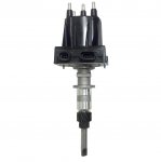
Indmar may muddy the waters, but here are the distributors

EST
Delco EST.jpg


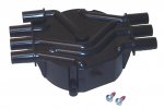
HVS Cap
HVS Cap.jpg

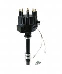
Thunderbolt

TB Dizzy.jpg
 

alldodge

Moderator
Staff member
Joined
Mar 8, 2009
Messages
42,591
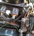
OK. my distributor looks like the EST example with 2 plug in connections...

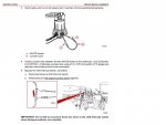
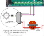
Cool, that will make it easy to use the shift interrupter. Need the connector that plugs into the one on the right with 4 pins. Then this will be used to set timing and also for shift interrupter. You will need 12V from a key active source, (purple wire possibly). Connect the 12V to the wire going to the long wire coming from the connector. Then put a jumper (b) between the (a) connections. Once timing is set, remove jumper and connect long wire to one side of switch and 12V to other side of switch

EST Timing.jpg
 

sasngang

Seaman
Joined
Jul 11, 2009
Messages
51
No Title

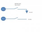
You guys ROCK!!! I do need some clarification... FIrst... I have 2 shift plates from carbed motors and they use a N.O. switch (Normally open), then when the switch is activated by the switch plate mechanism, the switch connects the coil to ground.

With this new information from #8... do I need to alter to a switch plate to use a N.C. switch (Normally Closed)? I believe so, please confirm.

I might need more info... see my photo attacched
 

Attachments

  • photo271407.jpg
    photo271407.jpg
    233.3 KB · Views: 4

alldodge

Moderator
Staff member
Joined
Mar 8, 2009
Messages
42,591
Same switch works for both. Old design had one side of the switch with a wire going to ground, new design it has the wire going to a 12V source. (can only be hot with ignition on).

The issue I'm having is finding a clear wiring diagram for the 350 Indmar, but I did find the ignition timing procedures.
https://www.bakesonline.com/images/MediaLibrary/IndmarIgnitionTiming.pdf

You will need to find the end of the wire which goes to the switch
 

sasngang

Seaman
Joined
Jul 11, 2009
Messages
51
OK... I'll see if I can pull the wire harness apart to determine what wires go where... Also, based upon the Timing document you referenced earlier, it seems the 4 connector plug that attaches to the right side of the distributor might have something to do with the crank position sensor. Really hoping we can come up with a meaningful electrical schematic.

As for the same switch being used on the Interrupt, my confusion is... IF I hook up the switch to swich 12vdc power (on one side), and since the current interrupt switch is NO (normally open = not switched on)... then, there will only be 12VDC going to the distributor when the switch actually activates... So how will adding 12VDC cause an interupt in the ignition system? I'm just challenged understanding.
 

kenny nunez

Captain
Joined
Jun 20, 2017
Messages
3,335
The bottom line is you will eventually have get the later style shift plate.
Also you may have to plumb the raw water intake through the bottom of the boat as was the original set up in the other boat. The Alpha 1 style pump is right on the edge of providing enough water for a 5.7.
 

sasngang

Seaman
Joined
Jul 11, 2009
Messages
51
Kenny... I wondered about the water provision... I do have the pump and am quite handy at glass work. Can you shed any light on where the pick-up should be located and does it have a special shape?
 

sasngang

Seaman
Joined
Jul 11, 2009
Messages
51
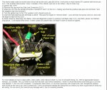
No Title

I did find a schematic that shows GM info for the 4 pins within that distributor.

In order to set base timing...
 

Attachments

  • photo271427.jpg
    photo271427.jpg
    21.7 KB · Views: 6
  • photo271428.jpg
    photo271428.jpg
    97.4 KB · Views: 4

sasngang

Seaman
Joined
Jul 11, 2009
Messages
51
No Title

Do you think this process could work to set base timing?
 

Attachments

  • photo271438.jpg
    photo271438.jpg
    268.9 KB · Views: 3

kenny nunez

Captain
Joined
Jun 20, 2017
Messages
3,335
There are 2 styles, one attaches to the transom and protrudes just below the bottom or the one that mounts near the pump inlet through the bottom. I just mounted one about 12" forward of the pump inlet that uses 1" pipe fittings on my 18' Donzi. You have to add a valve at the inlet . The main thing is to avoid the trailer boards or cause an air bubble too near the propellor. Google Rex Marine, Eddy Marine, Glenwood,Teague, etc and you will find what you need.
 

alldodge

Moderator
Staff member
Joined
Mar 8, 2009
Messages
42,591
The NO switch is used with either. The old Dizzy used points, the new uses an electronic pickup

switch.jpg
 

Fun Times

Moderator
Staff member
Joined
May 16, 2009
Messages
9,124
That is for a Merc MEFI 1 and 3 only
Which being he's using a 1997 TBI unit from Indmar, I do believe he should have a MEFI ECM from that old setup. I'm one my phone right now but if possible maybe you could show him the ECM's like you did with the Dizzy's above it might help narrow things down some. Plus if the OP could post a photo of his ECM too?

You guys are doing a good job at providing info.:)
 
Top