Hey, sqbtr, hooking up the DPDT lights to the ignition switch is a good idea, but only if he has an accessory position (like most cars do)or he'll only have lights to any of his switches when the ignition switch is left on (and engine electronics are charged up, constantly using power). I'd be interested in seeing the two battery source to the DPDT poles without a diode to prevent backfeeding through the wires. I'm not saying it can't be done, I just don't have my head around it.
Piece, the following comments are refering to the 2nd drawing in your Post # 356. I'll look at Post # 362 later.
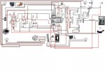
Judging by the way you have it wired, I assume you’ll use your battery selector to select your house battery when floating with the lights on and also use the battery selector to turn off the entire FUSE BLOCK = all lights (switch lights, NAV, STERN, etc) and disable both SPSTs, when parked on the trailer.
As drawn, when you turn on your DPDT to NAV (BOW & STERN), assuming you have a battery selected to the FUSE BLOCK, you ‘ll make both SPST switches glow red or white, depending on their position = OK. But your DPDT will never glow white, nor will your DPDT glow red when switched to the ANCHOR position. Also when the DPDT is in the ANCHOR position (only the STERN is lit) you’ll have no lights to the SPST switches, but they will still operate the BILGE and INTERIOR lights.
Let's assume a battery is selected to the FUSE BLOCK: To make the DPDT glow white in the center lever position, and make the DPST glow red when NAV is selcted (like it does now), and make the DPDT glow red when ANCHOR is selected, and make the SPST1 & SPST2 lights glow ONLY when the DPDT light glows red (either NAV or ANCHOR is selected), but the SPSTs not glow when the DPDT is white, change the following (I'm using clock positions again):
Remove the jumper wire between the 10:30 DPDT to 12:00 DPDT terminals. Replace with a 9:00 DPDT to 12:00 DPDT jumper wire. (Now DPDT will glow red/white/red, depending on lever position, whenever the FUSE BLOCK is powered by the BATTERY SELECTOR.)
Remove both 12:00 DPDT wires going to SPST1 & SPDT2, from the 12:00 DPDT side only, and reconnect them to the 1:30 DPDT location, with the other wire ends still attached to same SPST1 & SPST2 locations. (Now SPST1 & SPST2 will glow when DPDT is red, lever either up or down, and the SPSTs will not glow when DPDT is white, center position, when NAV and ANCHOR are off during the day, but SPSTs will still power their accessories during the day).
Is this the operation you are looking for?
You’ll still have to rotate the NAV/ANCHOR nameplate 180 degress, OR (my preference) rotate the DPDT switch 180 degrees (during dash install) because when you flip the DPDT lever UP the switch connects the center power to the LOWER terminals, and when you flip the DPDT lever DOWN it connects the center power to the UPPER terminals. (It’s easier to rotate something than redraw all the wires like I incorrectly tried in my long post above.) (Most double throw switches work this way).
This is not easy to put into words, so ask a question if something isn’t clear.
Todd


.jpg")