


Joe_the_boatman
Chief Petty Officer
- Joined
- Apr 14, 2005
- Messages
- 482
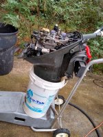
I picked up a fairly clean 1968 Johnson 9.5hp yesterday, and after adding fresh gas and putting it in a test tank, she started right up. Well, sort of. Ran rough, raw fuel was coming out the exhaust, and then died when throttled down. I checked spark (inline spark tester, air gap) and got spark on bottom cylinder but none on top. Ran a minute or two more just for grins, and then lost spark on both cylinders! Packed it up and called it a day.
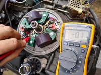
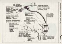
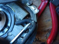
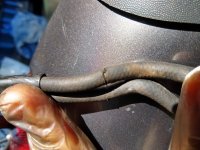
Today, pulled flywheel to check magneto. It was all super clean, points looked clean, no cracked coils, wires in good shape, all connections tight.
Primary resistance on each coil (to spark plug boot) measured 4.16kΩ & 4.17kΩ, which told me wires and (probably) coils were OK. Swapped condensers, top still had no spark (but at least it ran, the bottom had spark again), so condensers are OK. Cleaned points with 200, then 500 grit sandpaper, set gap to 0.020".
(As an aside - Fluke's "Troubleshooting Outboard Motor Magneto Ignitions" guide says "In any event do not use sandpaper. The grit will imbed itself in the contact metal, rendering the points useless." While leeroysramblings.com says "Best way to clean points is to...Use a strip of 400 grit (black) sandpaper... and polish them shiny bright." I went with Leeroy on this one, but if they're ruined, I'm ready to replace them anyhow).
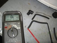
Back to the issue.... Once points were cleaned, resistance across contacts measured:
Points open: ~1.0Ω.
Points closed: 0.0-0.1Ω
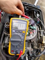
Inline spark checker showed spark on both cylinders. Attached wires to plugs and it ran great (both cylinders firing) for about 30 seconds, then sputtered (running on one cylinder) and died when throttle reduced to idle. Raw fuel in exhaust. Checked spark again, and top cylinder again had no spark. Dang!
Swapped spark plugs and coils, the only parts left between the two systems that haven't been swapped. Cleaned points again and set to 0.020". Meter showed 0.0-0.1Ω again with points closed. Double checked all connections and buttoned her back up.
Started it up, but still no spark on top cylinder. So, no change.
What am I missing here? I swapped everything from the running cylinder to the dead one (except plug wires and points, which tested OK with a meter), and still have a dead cylinder. I don't like throwing new parts at undiagnosed ignition problems, but don't know what else to do here. I could probably replace everything for around $100, but that's what I paid for the whole engine.
(PS - Before someone suggests it, I didn't get the plug wires mixed up - one has a metal tag stamped "TOP").
So, what next?
Video, running on one cylinder, for grins:
Today, pulled flywheel to check magneto. It was all super clean, points looked clean, no cracked coils, wires in good shape, all connections tight.
Primary resistance on each coil (to spark plug boot) measured 4.16kΩ & 4.17kΩ, which told me wires and (probably) coils were OK. Swapped condensers, top still had no spark (but at least it ran, the bottom had spark again), so condensers are OK. Cleaned points with 200, then 500 grit sandpaper, set gap to 0.020".
(As an aside - Fluke's "Troubleshooting Outboard Motor Magneto Ignitions" guide says "In any event do not use sandpaper. The grit will imbed itself in the contact metal, rendering the points useless." While leeroysramblings.com says "Best way to clean points is to...Use a strip of 400 grit (black) sandpaper... and polish them shiny bright." I went with Leeroy on this one, but if they're ruined, I'm ready to replace them anyhow).
Back to the issue.... Once points were cleaned, resistance across contacts measured:
Points open: ~1.0Ω.
Points closed: 0.0-0.1Ω
Inline spark checker showed spark on both cylinders. Attached wires to plugs and it ran great (both cylinders firing) for about 30 seconds, then sputtered (running on one cylinder) and died when throttle reduced to idle. Raw fuel in exhaust. Checked spark again, and top cylinder again had no spark. Dang!
Swapped spark plugs and coils, the only parts left between the two systems that haven't been swapped. Cleaned points again and set to 0.020". Meter showed 0.0-0.1Ω again with points closed. Double checked all connections and buttoned her back up.
Started it up, but still no spark on top cylinder. So, no change.
What am I missing here? I swapped everything from the running cylinder to the dead one (except plug wires and points, which tested OK with a meter), and still have a dead cylinder. I don't like throwing new parts at undiagnosed ignition problems, but don't know what else to do here. I could probably replace everything for around $100, but that's what I paid for the whole engine.
(PS - Before someone suggests it, I didn't get the plug wires mixed up - one has a metal tag stamped "TOP").
So, what next?
Video, running on one cylinder, for grins:
Attachments
Last edited:

") thanks for your feedback !
thanks for your feedback !