Pull the positive wire off the coil. Turn ignition to run. Measure the resistance between that wire and the positive battery post and report back.
Bruce,
Hope I measured the resistance right, but I got .00 to.01??
1. Mechanic ran a wire (White) straight from key ignition to coil. (to try and solve issue)
2.Also spliced in purple resistance wire to coil (red going into purple), before harness to engine.
3. Removed original purple/yellow wire from starter and purple resistance wire and tucked it under harness.
4. Sierra coil that requires external resistor in place. Electronic ignition put on (Sierra) 4cyl Mercruiser 3.0 engine.
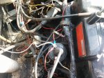
Second pic shows that he removed the purple/yellow and purple wire from the coil, but only tucked it under the harness.
Thanks
Bruce,
Hope I measured the resistance right, but I got .00 to.01??
1. Mechanic ran a wire (White) straight from key ignition to coil. (to try and solve issue)
2.Also spliced in purple resistance wire to coil (red going into purple), before harness to engine.
3. Removed original purple/yellow wire from starter and purple resistance wire and tucked it under harness.
4. Sierra coil that requires external resistor in place. Electronic ignition put on (Sierra) 4cyl Mercruiser 3.0 engine.
Second pic shows that he removed the purple/yellow and purple wire from the coil, but only tucked it under the harness.
Well, since he put in that white wire, that's your issue. He probably then branching off from there to the ignition module and that is why he was having problems when the resistor wire was in there. Goes to show you, anyone can call themselves a mechanic these days.
Where are the other 2 wires going?
Out of curiosity, what is the resistance of that purple wire to the positive battery post with ignition on?
")
Hmmm..... OK what scale did you have the multimeter on? You are only trying to measure about 1 ohm, so you need it on the lowest scale.
OK, so your 1) guy bypassed the resistance wire, and 4) you need external resistance. If that white wire is still in place that is wrong! The purple yellow wire from the starter is what bypasses the resistance (purple) wire during starting. 2) is strange, red wires are unswitched battery voltage, so that wire would have voltage on it all of the time?? So you need to get rid of the white wire and hook up the purple (purple being ignition switched voltage) and the p/y wire back up to the coil+. Now you need to find out what the correct voltage for the module is. Does it take 12 volts or the reduced voltage from the resistance wire?
OK as best as I can find out that is a Petronix Ignitor. So you need to have the resistance wire in place for the coil. Now that module needs the full 12 volts to operate correctly. Try this: remove the white wire and the red module wire from the coil and splice them together ( this will give you 12v for your module). Replace the purple resistance wire and the p/y wires on the coil + and you should be OK. I hope. One note, if you leave the ignition on the module could burn out because it is not protected as opposed to the IgnitorII which is. Good luck.
With the multimeter on 20 you should have read something over 1 ohm. The resistance wire runs from a connector on the electric choke to the + terminal of the coil. To measure correctly: you would remove the wire from the coil, with the key OFF, put one probe on the choke connector and the other on the end of the purple wire. Read the resistance on your lowest scale, probably 20.
That is what it is supposed to be with a resistor in there.I did measure the voltage when the key was on run, at the coil. It measured 8-9 volts.
That is what it is supposed to be with a resistor in there.
When you measured resistance, you did take the wire off the coil when you measured it right?
The measurement of resistance I measured was from the white ignition to the positive battery terminal. I will measure the resistance you just advised and let you know. The coil is supposed to get 12v at start up and then reduced afterwards. I did measure the voltage when the key was on run, at the coil. It measured 8-9 volts.
The voltage at the coil depends on if the pertronix switch is closed or not. If its closed and there is a resistor wire in there, it should 8V.Couple of measurements to make: voltage between the two battery terminals, and voltage between the end of the white wire ( key on) and a good engine ground. They should both read the same, somewhere around 12.8 volts for a fully charged battery. Yeah the coil gets full battery voltage at startup (will be less than 12 v because of the large current draw by the starter) and when the key returns to run, the coil gets reduced voltage through the resistance wire.
The voltage at the coil depends on if the pertronix switch is closed or not. If its closed and there is a resistor wire in there, it should 8V.
That's what he said he measured before in his post #31.
Having the wire disconnected when measuring voltage tells you basically nothing. It's going to measure battery voltage.The white wire should have been removed from the coil, so it should read battery voltage from the ignition with the key on. The resistor wire will be getting voltage from the choke connector and will not be in the circuit.