Mercruiser 470 Cam Seals 1985 Sea Ray Monaco 185

Alterry

Cadet
Joined
Sep 1, 2014
Messages
22
This thread is an update of numerous threads, some more than ten years old with a wealth of information on replacing the cam seals in the veritable 470 engine, some of which may still be around. I added a little of my own insight and experience, but I owe a debt of thanks to all those posters who have gone before.

I ordered a 27-68714A7 gasket kit from boats.net. I ordered the 26-97530 water seals and the 26-67388 front crankshaft seal from a local mercury dealer, trying to stick with OEM on those as been suggested on an earlier thread. Best to have the parts on hand before you start this project as they are often back ordered. If you are just discovering the weep hole leak you probably have some time before the rear seal goes, so keep an eye on the oil on the dipstick and get the parts plus block some time to do the repair properly.

The sealant numbers have changed a little, but high strength locktite, or locktite red is equivalent to Loctite 8831, loctite 271 and loctite 263.

Quicksilver Perfect Seal is equivalent to Permatex Aviation form a gasket

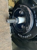
I used Permatex sleeve retainer for the speedy sleeves.

The other sealants are as specified I believe, but here is a picture of what I used3B53CDE2-76EE-47A9-8FFC-25F1FD8323F4.jpeg
2989E2AA-0E66-4B21-9AF9-4D0C417451FD.jpeg
The link to sterndrive.com is:
 

Alterry

Cadet
Joined
Sep 1, 2014
Messages
22
Before I started this project I noticed all of the available information addressed raising the engine with a hoist if the center of the crankshaft was below the deck. A hoist isn’t necessary if you can raise the motor high enough using the alignment adjusting stud. You first must remove the stern drive unit, but this is true if you use a hoist as well, any pressure on the driveshaft could easily damage the engine coupler. At the end of the repair, recheck the engine alignment and install the stern drive unit.


I took a picture of the adjusting studs position in relation to the front mount bracket before I raised the engine with the adjusting stud so I would have an idea where to start when I aligned the engine after the repair.
 

Attachments

  • 3866CF96-F512-4E7B-B301-C0C847E33746.jpeg
    3866CF96-F512-4E7B-B301-C0C847E33746.jpeg
    1.8 MB · Views: 7
  • C6CF9116-98D6-402E-A1CE-6BA9DE8A1D02.jpeg
    C6CF9116-98D6-402E-A1CE-6BA9DE8A1D02.jpeg
    1.8 MB · Views: 7
Last edited by a moderator:

Alterry

Cadet
Joined
Sep 1, 2014
Messages
22
Like others doing this repair I struggled with how much room I would need to pull the harmonic balancer forward even after I raised the center of the crankshaft high enough to get the puller on. As it turns out, the harmonic balancer only moves 2 1/4” forward before it clears the crankshaft, so if you have about 3” between the harmonic balancer and front of the engine compartment you should be in good shape even after you factor in the thickness of the harmonic balancer puller.

One advantage of having the front mount in place when you do this repair is it gives you something to wedge a block of wood into when remove or install the bolt that holds the harmonic balancer on the crankshaft. It takes 75 lbs of torque, so it can be a challenge to get the harmonic balancer to stay put.

I found a harmonic balancer puller at O’Reillys, and an installer as well. I did not have to make my own installer, both kits worked really well and were available as rentals. They only cost about $25, so buying these is a viable option as well.
 

Attachments

  • E289E922-6921-4DDE-B35B-CFFF26706672.jpeg
    E289E922-6921-4DDE-B35B-CFFF26706672.jpeg
    1.9 MB · Views: 5
  • 7C5C2F84-0432-4CB0-9DDE-C5C2C111C068.jpeg
    7C5C2F84-0432-4CB0-9DDE-C5C2C111C068.jpeg
    2 MB · Views: 7
Last edited by a moderator:

Alterry

Cadet
Joined
Sep 1, 2014
Messages
22
I had no issues removing the stator Allen screw s. I have an alternator, so I simply set the stator aside and did not reinstall it.

My impeller was also easy to remove, I heated it first to break any locktite that might have been there and it came right off.

My water pump cover came off in two pieces, courtesy of a Rube Goldberg alternator installation that relied on a single stud in the cover to hold the alternator brace. I can’t complain too much, this lasted about ten years before it started to leak, and a little JB weld got me through the last twenty. I found a replacement on eBay for about $40.00.
 

Attachments

  • 53351E84-0ED2-4C17-B0F2-274829297D96.jpeg
    53351E84-0ED2-4C17-B0F2-274829297D96.jpeg
    4.5 MB · Views: 11
  • B430D360-BE80-48FA-9DD1-1E31A94E6B98.jpeg
    B430D360-BE80-48FA-9DD1-1E31A94E6B98.jpeg
    3.4 MB · Views: 12
Last edited by a moderator:

Alterry

Cadet
Joined
Sep 1, 2014
Messages
22
I removed seven screws from the oil pan gasket, three go into the the timing cover and I removed two on either side to try to make separating the oil pan gasket from the timing cover easier. I don’t think it helped much. I worked the razor blade between the timing cover and oil pan gasket as best I could, as others have said it’s tedious and you have to go slow. When I finished this I began to remove the timing cover using a putty knife to start with on either side, until I got it far enough back to use a screwdriver. (The alignment pins they mention are on either side of the block just above the oil pan) I checked the gasket just before I pulled the timing cover all the way off and it had separated from the timing cover cleanly.
 

Attachments

  • 49B4AC52-6802-414D-99B6-CDCD024A748C.jpeg
    49B4AC52-6802-414D-99B6-CDCD024A748C.jpeg
    4 MB · Views: 13

Alterry

Cadet
Joined
Sep 1, 2014
Messages
22
I removed the timing cover and took a picture of the position of the cam seals. I wanted to duplicate this, particularly the front seal, when I installed the new seals so I could be certain they would be positioned over the speedy sleeve. My front seal is located at the base of the chamfer in the timing cover, so not quite flush with the front of the cover.

At this point all of the mating surfaces were exposed so I began scraping the old gasket material off with a razor blade and scotchbrite. It is a bit of a pain, but you just have to take your time and get everything as clean as you can. Be careful around the engine block that you don’t get material in the engine that doesn’t belong there.

It’s also a good time to look at the timing cover and impeller cover and understand where the different bolts will go when it’s installed. There are four short bolts that just screw into the timing cover, the other long bolts go through both the impeller cover and the timing cover into the block. There are also four short bolts, two on either side of the bottom of the timing cover that only go through the timing cover into the block.
 

Attachments

  • 1953B4E9-6157-4E21-A9DA-326A0D93927B.jpeg
    1953B4E9-6157-4E21-A9DA-326A0D93927B.jpeg
    947.5 KB · Views: 15
  • 904C1BE7-7CE7-4D07-AF0D-1C7556DA7B43.jpeg
    904C1BE7-7CE7-4D07-AF0D-1C7556DA7B43.jpeg
    1.5 MB · Views: 13
  • B6926EF1-D5C6-4250-AB03-AC09866B7E81.jpeg
    B6926EF1-D5C6-4250-AB03-AC09866B7E81.jpeg
    1.7 MB · Views: 14
Last edited by a moderator:

Alterry

Cadet
Joined
Sep 1, 2014
Messages
22
I’m going to try to capture all of the concerns pressing the seals in and out I came across in the various threads on this forum, that way there in one place. The timing cover has a lip on the back where the rear water seal seats. So the water seals can only be pressed or punched out one way, they go out through the front and are pressed in from the front side. The spring side of the seals is the sealing side, so the water seals both face forward, or in the direction of the water pump cover. The front seal keeps the water from leaking out of the cooling system and the rear seal keeps the water out of the engine should the front seal fail.

It is important to support the opposite side of the cover where the seals are installed whenever you remove or install the seals. This is because the seal cavities do not lay flush when the cover is on its side on a bench or table. If you press or tap on the seals without support around the seal cavity on the opposite side you can easily crack the timing cover. I found a thick spacer slightly larger than the cavity that worked fairly well.

Similarly the front seal or oil seal, seals with spring side facing the engine. In this case the lip is on the seal itself, so it also goes in from the front, but facing in the opposite direction of the water seals as it keeps the oil in the crankcase.

Bottom line is all seals are pressed out from the back (engine side) and pressed in from the front ( water side). Water seals face forward and front (oil) seal faces rearward, the spring side is always the sealing side.
 

Attachments

  • 0AACC567-7489-4082-9002-6156315150BD.jpeg
    0AACC567-7489-4082-9002-6156315150BD.jpeg
    2.2 MB · Views: 9
  • 0A2FCFB5-0485-4A1C-8D6E-37A32C193930.jpeg
    0A2FCFB5-0485-4A1C-8D6E-37A32C193930.jpeg
    1.5 MB · Views: 10
  • AFB208B1-9DC9-435F-B844-34E395477729.jpeg
    AFB208B1-9DC9-435F-B844-34E395477729.jpeg
    1.8 MB · Views: 9
Last edited by a moderator:

Alterry

Cadet
Joined
Sep 1, 2014
Messages
22
I used a hammer and punch to remove the water seals and a hammer and PVC coupling to remove the front (oil) seal. I used a hammer and a device that was just slightly less than the diameter of the water seal cavity to install the water seals. I could not find a PVC piece close enough to the cavity diameter, so I did some rummaging around in the old coffee can of junk I have in garage and got lucky. The problem is what ever you use should press on the outside of the seal but still be small enough to fit in the cavity. For the front (oil) seal I just used a PVC coupling for the install as well.

I could not come up with a make shift press, so I used a hammer to install the seals. If I had it to do over again I would spend more time fashioning or getting a press. It takes more force than I was really comfortable with to get the seals in place using a hammer, and while I supported the seal cavity’s fairly well, I think I was lucky not to crack the cover. It’s not that robust to begin with and all of 35 years old.

I was careful to put the front water seal in the same location in the timing cover as the front water seal I removed. The rear water seal seats against the lip in the timing cover.
 

Attachments

  • 33DF63E1-2FE8-41EB-80AD-5AE448009EFC.jpeg
    33DF63E1-2FE8-41EB-80AD-5AE448009EFC.jpeg
    2 MB · Views: 11
  • 53C57176-78C9-468D-BDE9-8D05EB3D7539.jpeg
    53C57176-78C9-468D-BDE9-8D05EB3D7539.jpeg
    2.1 MB · Views: 10
Last edited by a moderator:

Alterry

Cadet
Joined
Sep 1, 2014
Messages
22
As far as the camshaft is concerned, I found the same deep groove under the front water seal as others have documented, and similar light groove where the rear water seal rode. I used a micrometer to measure the camshaft and came up with .873 and some change as have others, the low end of the SKF 99087 dimension range, just like every one on every other thread. My question is aren’t we all over thinking this? How many different diameter sleeves will a 97530 water seal fit over and how many different camshafts are on a 470 engine? It’s not as if we are measuring for wear, the directions for the speedy sleeve specially state to measure in a non wear area.

I’m not saying don’t measure, this is a fair amount of work and you want to get it right, but if you’re result leads you to order something other than a SKF 99087 you might want to double check everything.

The SKF recommendation on the installation of speedy sleeves is to leave the installation ring in place unless it necessary for removal, so I opted to leave it place for the rear installation.

The SKF installation recommendation also says:

“If the flange is to be removed, it should be cut from the outside diameter into the radius in one location prior to installation.”

I did not see this in any of the other threads or the sterndrive.com instructions. It might make removal of the installation ring go a little smoother.

I’d like to say I read this before I installed my speedy sleeves, but I came across it after. I was able to remove the installation ring on the front sleeve without too much trouble, but I found it was worth it to buy a new pair of dykes to get a clean cut.

Driving the seals in place was straight forward using the tool in the kit. I used Permatex sleeve retainer which will make up a .007 gap and it worked really well.
 

Attachments

  • 2F1DE402-2E47-48A0-B1C4-60AC5771A29D.jpeg
    2F1DE402-2E47-48A0-B1C4-60AC5771A29D.jpeg
    2.4 MB · Views: 26
  • 7E2027C6-B47E-4B87-A89F-6CE9151B73FD.jpeg
    7E2027C6-B47E-4B87-A89F-6CE9151B73FD.jpeg
    1.3 MB · Views: 26
  • E85C14FF-465C-482D-9123-4B269773DEBA.jpeg
    E85C14FF-465C-482D-9123-4B269773DEBA.jpeg
    1.4 MB · Views: 27
  • FE37E743-2510-4B9E-BA78-353260616C63.jpeg
    FE37E743-2510-4B9E-BA78-353260616C63.jpeg
    1.4 MB · Views: 29
Last edited by a moderator:

Alterry

Cadet
Joined
Sep 1, 2014
Messages
22
My chain tensioner was worn pretty bad so I replaced it with a less worn one I found on eBay. The timing chain and gears seemed other were in good shape.

The exposed oil pan gasket was fairly intact and there was no gasket material on the timing cover, so I was more fortunate than others as far as this was concerned. I coated the gasket and timing cover flange that mates with the gasket with Permatex non hardening sealant, putting a little extra in the corners as recommended, and this seems to have worked.

I think the main concern when you separate the timing cover from the block is that you don’t pull the gasket from the block as you remove the timing cover, in other words damage the gasket in the areas adjacent to the timing cover under the block. If you do, you may need to remove the oil pan and replace the gasket. But if you get the timing cover off cleanly you can easily replace the gasket material under the timing cover if it’s damaged with new gasket material and sealant. How thick the new material should be is an issue, I’ve yet to see someone post the OEM thickness. Don’t go by the thickness of the old material though, at least some swelling must take place and at least one individual had a problem with the material being too thick according to a post a number of years ago.
 

Attachments

  • 8EFC24BE-5C73-48BD-8AC4-494EAF941D06.jpeg
    8EFC24BE-5C73-48BD-8AC4-494EAF941D06.jpeg
    1.8 MB · Views: 17
  • 44F73989-56CC-475E-99D8-40DBC8A5180D.jpeg
    44F73989-56CC-475E-99D8-40DBC8A5180D.jpeg
    4.1 MB · Views: 19
  • 80B563BD-FE1B-4A1A-B107-5CC4155E3BE6.jpeg
    80B563BD-FE1B-4A1A-B107-5CC4155E3BE6.jpeg
    4 MB · Views: 17
Last edited by a moderator:

Alterry

Cadet
Joined
Sep 1, 2014
Messages
22
I ordered a gasket kit from Mercury prior to starting this and I used Permatex Aviation gasket instead of perfect seal on all the mating surfaces as I believe others have done. My timing cover went on easily, I tried to be careful to get it on evenly. Once it was in place the cam seals appeared to be out of place, but this corrected itself once the cover was tightened.

I tried to start all the bolts before tightening anything including the bolts coming up through the oil pan. After about 20 minutes of choice words and weeping and whaling I realized the holes needed the oil pan won’t line up with the timing cover until the timing cover is tightened to the block. After tightening the bolts on the timing cover the bolts easily screwed in by hand.

I used loctite 263 on the impeller bolt and torqued it twenty lbs. As I tried to tighten the bolt the impeller hit the timing cover as the timing cover had not been torqued yet, the impeller cover still being off. This was not an issue anyone else had that I read about, but it’s a little bit of back and forth before you can get final torque on everything.

I put the impeller cover on and torqued all the bolts alternating from one side to the other to fifteen lbs, except the oil pan bolts are 11 lbs (130 inch lbs).

I checked the torque on the impeller once more before putting the hose cover on. It was fine and this may be the best time to torque the bolt, after everything else is installed.
 

Attachments

  • 449DDEB7-DB8E-45F7-B64E-6D53804A1B4C.jpeg
    449DDEB7-DB8E-45F7-B64E-6D53804A1B4C.jpeg
    1.1 MB · Views: 10
  • F04C8D4A-83DF-41C1-B39A-9B4F69C9DE86.jpeg
    F04C8D4A-83DF-41C1-B39A-9B4F69C9DE86.jpeg
    3.2 MB · Views: 9
Last edited by a moderator:

Alterry

Cadet
Joined
Sep 1, 2014
Messages
22
I put the hose connector cover on and torqued it to fifteen lbs and cracked the cover in the process. Fortunately I had another cover that came with the impeller cover I got on eBay, so after another gasket cleaning drill I put this one on and just tightened it to what felt right and it hasn’t leaked so far. Fifteen lbs is what the manual calls for, but these screws are pretty small and the covers getting pretty long in the tooth, as am I 😊

I did not put the stator back on as I have an alternator, so next step was to put the harmonic balancer on. I used a kit from O’Reilly’s, which had a 1/2 by 20 adapter, the same thread size as the center bolt. I had to use a two inch piece of one inch PVC between the jack screw not and the pressure bearing so I could swing the wrench. Otherwise this kit worked fine. Just make sure you have adequate thread engagement on the adapter before you start to press on the harmonic balancer.

I coated the crankshaft end with Permatex aviation form a gasket, made sure the harmonic balancer was in the key on the crankshaft and used the kit to drive it the rest of the way on. Once it was on I put the center bolt in and torqued it to seventy five lbs, using a block of wood between the front mount bracket and harmonic balancer to keep the crankshaft from turning. Once I had it torqued I removed the wood and turned the the crankshaft to make sure nothing was rubbing, and then I checked the clearance between the harmonic balancer and the block.
 

Attachments

  • 9BE0EBAD-D44F-4B50-BAB0-3584B32F879A.jpeg
    9BE0EBAD-D44F-4B50-BAB0-3584B32F879A.jpeg
    1.5 MB · Views: 13
  • 09ED3C59-A552-4327-8032-0BA2641DF0C3.jpeg
    09ED3C59-A552-4327-8032-0BA2641DF0C3.jpeg
    2.1 MB · Views: 14
  • E266C7F3-0F55-40E6-A14A-ADC27CE7B546.jpeg
    E266C7F3-0F55-40E6-A14A-ADC27CE7B546.jpeg
    3.2 MB · Views: 11
  • 20702AC7-A251-4F64-B46F-D4652F7751FD.jpeg
    20702AC7-A251-4F64-B46F-D4652F7751FD.jpeg
    2.5 MB · Views: 10
  • F403B3DD-F3B0-4152-84E9-327C038F9EA0.jpeg
    F403B3DD-F3B0-4152-84E9-327C038F9EA0.jpeg
    2.1 MB · Views: 9
Last edited by a moderator:

Alterry

Cadet
Joined
Sep 1, 2014
Messages
22
I changed both drain plugs on the heat exchanger since they were easy to get at and I had the coolant drain out anyway. I put them in and the lowered the engine to the starting position with the adjusting stud. I put the lower nut and jam nut back on, leaving them loose until I checked the alignment. After I aligned the engine I tightened the nuts on the adjusting stud and installed the stern drive unit.
 
Last edited by a moderator:

Alterry

Cadet
Joined
Sep 1, 2014
Messages
22
The whole project took me around 25 hours including the removal and installation of the stern drive unit. It was actually kind of a fun project, but you need some time to do it. Someone suggested about 4 hours on a previous thread, no way! Also don’t forget to use a drop of high strength locktite on the outside of the seals when you press them in, and a generous amount of 2-4-C on the seals, crankshaft and camshaft surfaces where the seals ride.
 
Last edited by a moderator:
Top