Mercruiser 7.4 MPI Alarm Sounding, but everything seems fine???

alldodge

Moderator
Staff member
Joined
Mar 8, 2009
Messages
42,539
Some came with two sensors and some only one, mine came with only one and it's on the starboard side. You are correct that it is the same wire tied together so one is plenty.

As before, it will be good to find out the reason for the buzzing but if its the oil pressure switch or lube bottle I don't see a code being found. Hope the scan comes up with something

Ya know, you code unplug the buzzer, but if something else happens you would not be notified, just watch the gauges
 

Lucrative

Petty Officer 3rd Class
Joined
May 8, 2015
Messages
96
I did test the gear lube previously and that appeared to be fine, so I guess best guess is the oil pressure switch. Ill probably try to test that before bringing it in. Haven't gotten to it since I found out where it is....more tomorrow
 

Lucrative

Petty Officer 3rd Class
Joined
May 8, 2015
Messages
96
So, tested the oil pressure switch, got a .26 resistance when engine not running, and 1 when engine was running, so it seems that is good, right?. I also realized that the temp sensor attached to my thermostat housing is running my temp gauge....I thought this wasn't supposed to be the case. I thought the temp sensor under the thermostat housing running into the block was supposed to run the gauge. I'm confused. Are those sensors locations switched?

Edit: Put 40 gallons of 89 in it, but haven't gotten to run it yet to see if it might be a knock. I might be looking for the location on that alarm soon.......but gonna get it hooked to the scanner first.
 
Last edited:

alldodge

Moderator
Staff member
Joined
Mar 8, 2009
Messages
42,539
So, tested the oil pressure switch, got a .26 resistance when engine not running, and 1 when engine was running, so it seems that is good, right?.

Getting .26 ohms with it not running is good, but 1 ohm when running is bad. You should get an open circuit or in the area of at least 1 Meg ohm, if not 10 meg.

I also realized that the temp sensor attached to my thermostat housing is running my temp gauge....I thought this wasn't supposed to be the case. I thought the temp sensor under the thermostat housing running into the block was supposed to run the gauge. I'm confused. Are those sensors locations switched?

You should have 2 senders, one is a switch and one is a sender which goes to the gauge. The wire going to the gauge should be Tan in color

Edit: Put 40 gallons of 89 in it, but haven't gotten to run it yet to see if it might be a knock. I might be looking for the location on that alarm soon.......but gonna get it hooked to the scanner first.

It should be on the engine
 

Lucrative

Petty Officer 3rd Class
Joined
May 8, 2015
Messages
96
Getting .26 ohms with it not running is good, but 1 ohm when running is bad. You should get an open circuit or in the area of at least 1 Meg ohm, if not 10 meg.

The setting it had it on, 1 was an open circuit. It read 1 whether I had the connectors completely apart or if they were touching the ground and the oil switch. Not really sure what setting I should have it on when testing this stuff.....I've got 2m, 200k, 20k, 2k, 200.

Gotta check into the sensors....The one with the plastic plug and clip goes underneath the t-stat. The one with the 90 that just pushes onto the metal stud goes into the side of the t-stat....so that should be the switch I thought...but it seems that it's running the gauge.

Also, the alarm sounds like it's coming from somewhere in my dash.
 

alldodge

Moderator
Staff member
Joined
Mar 8, 2009
Messages
42,539
The setting it had it on, 1 was an open circuit. It read 1 whether I had the connectors completely apart or if they were touching the ground and the oil switch. Not really sure what setting I should have it on when testing this stuff.....I've got 2m, 200k, 20k, 2k, 200.

Gotta check into the sensors....The one with the plastic plug and clip goes underneath the t-stat. The one with the 90 that just pushes onto the metal stud goes into the side of the t-stat....so that should be the switch I thought...but it seems that it's running the gauge.

Also, the alarm sounds like it's coming from somewhere in my dash.

Should use the 2M scale for running

Sounds good, with your alarm under the helm, many are not. Either way as before there is a one bayonet plug which could be pulled to silence, but as before this could be an issue if something else happens.
 

Lucrative

Petty Officer 3rd Class
Joined
May 8, 2015
Messages
96
Alrighty everyone, finally got it to the marina and got the scanner attached to it. It came back with a code 44 knock sensor. (knock sensor inactive) I have recently replaced the one knock sensor that I thought was bad with an A/C Delco knock sensor that came up when I cross-scanned the part number. I also put 40 gallons of 87 in with my existing ~40 gallons of 93.

This leads me to believe there is something with the wiring. Either both of those sensors need to be connected for it to get the right resistance reading, or I've got a break between the existing sensor and the ecm, or, for some reason, the A/C Delco knock sensor is not compatible for some reason.

Where do I start with this? I don't have the wire that would connect the 2 knock sensors. I believe, after looking at the wiring diagram, that it runs from starboard side sensor to the port side sensor to the ecm. I'm missing the connection between the 2 sensors.

Any way to check if I've got a good connection between the knock sensor and the computer?
 

alldodge

Moderator
Staff member
Joined
Mar 8, 2009
Messages
42,539
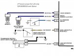
Was a bit in error when first looked. The only engines with two knock sensors and attached to one wire is those with a MEFI-2 ECM. You have a MEFI-3 so you should have the setup listed below. Use an ohm meter and ring out the connections. Since you replaced the one, you could swap it with the other side if the ohm reading verifies a good connection

1knock l29 sensor.jpg
 

Lucrative

Petty Officer 3rd Class
Joined
May 8, 2015
Messages
96
In the manual I found online, it showed them both running on the same wire. I was probably looking at the wrong manual. There's a lack of information online about this engine in particular it seems, and a lot of misinformation. It's so similar to those made before and after it, it was only made for 2-3 years, and there are many shared traits. Makes getting the proper information really hard and frustrating because I don't have the original service manual.

I believed this http://boatinfo.no/lib/mercruiser/manuals/mercruiser23.html#/810 to be my manual. Am I looking at the wrong one? Pg. 810 shows the knock sensor on one wire.

Anyways, I only currently have one wire running to my port side knock sensor (the one I replaced). The other sensor has no wire running to it and I have no idea where the wire and connector are and when, why, or how it might have been removed.

Can you help me understand the diagram? What does the 496 and the J1-30 and J1-14 signify?
 

alldodge

Moderator
Staff member
Joined
Mar 8, 2009
Messages
42,539
Your looking at the correct manual. If you go to page 640 you will see what I posted. The section your looking at is the most common and they do not show the one I posted. The post is for the L29 version only, so you having two sensors could have been it. I have a MEFI 3 and only one knock sensor, not an L29 version.

The code 44 in any event is that the computer tried to verify the knock sensor was working and found it was not. This is done thru the wire leading to it. What you need to do is disconnect the battery, remove the ECM connector J1 and ohm out the connection between the pin to the sensor. My guess with corrosion it may not be making contact.

I hope someone didn't cut the wire leading to the second sensor so look for a wire connected to J1-14
 

Lucrative

Petty Officer 3rd Class
Joined
May 8, 2015
Messages
96
So, I realize this is somewhat ridiculous that I'm this far along in this process and with everything else I've done to the engine, I feel really dumb asking, but I'm having trouble identifying where the J1-14 and J1-30 connections are. Can you point me in the right direction?
 

Lucrative

Petty Officer 3rd Class
Joined
May 8, 2015
Messages
96
Closing up the topic. Both knock sensor wires needed to be connected in my case. Once I got wires running to both sensors, the issue cleared up. Man that was a long way around for a wire. Thanks for sticking with me, everyone.
 
Top