tigger3650
Petty Officer 2nd Class
- Joined
- Apr 7, 2012
- Messages
- 130
The water passage O-ring was separate. I have seen some shafts with the 2 O-rings near the u-joint and a third closer to where it enters the coupler.


This brings up another thought. The boat is an '85, the motor came out of a' 90'sish Bayliner. They left my outdrive and transom assembly and said they couldn't put the newer one in because the cutout in my transom was bigger than the one required for the newer one. I was not about to replace the transom, again. I was wondering if there is a difference here?
Too short, I would think it would pull from the splines?
Assuming the newer boat had an alpha 1 gen 2, you'd need to replace the transom assembly, bellhousing, etc. Cutouts AFAIK are identical. Shouldn't be your issue.
Too short and it destroys your coupler.
Just out of curiosity, where are you going with this?
The transom assemblies are clearly different. ...
The cutouts are the same though.Assuming the newer boat had an alpha 1 gen 2, you'd need to replace the transom assembly,
I believe that nothing between the engine and the transom assembly should be different though correct?
They may have pulled the bell housing and such off of my old motor and put them on the new one. Not exactly sure

Correct. everything except the motor is original (at least when I bought it). The S/Ns on the drive and transom assembly reference Alpha 1 Gen 1.Just read through the thread, and we actually don't know what you have. I assumed that you still have your original drive, which should be alpha one. If that's the case, then you still have everything original from the transom assembly aft.
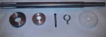
Here's a pic of the tool end I made to let me press the bearing cup out. In the drawing it is shown in blue, with the bearing nut shown in yellow and the u-joint cup shown in green. I did have to knock the corners off my older drive, while the newer one has plenty of clearance. The cutouts on the tool support the press and keep things square while the press is pushing. This is using a simple ball end press.
Here's a pic of the tool end I made to let me press the bearing cup out. In the drawing it is shown in blue, with the bearing nut shown in yellow and the u-joint cup shown in green. I did have to knock the corners off my older drive, while the newer one has plenty of clearance. The cutouts on the tool support the press and keep things square while the press is pushing. This is using a simple ball end press.
That's cool. I actually thought about doing something like this when I just did the u-joints, looks like it would work well. achris , could we put a link to this tool in the diy tool section?
")
This
...During the cleaning process, it felt like there was a gap behind the gimbal bearing so we decided to whack it a few more times with the bearing/ alignment tool. Now the alignment is out....
The bearing tool I have attaches to the alignment bar. There is a pin that holds it in place on the shaft. It has the rings around it that put equal pressure on the bearing, Similar to the ones used on autos.