More Battery switch Panel Pics

drewpster

Commander
Joined
Oct 17, 2006
Messages
2,059
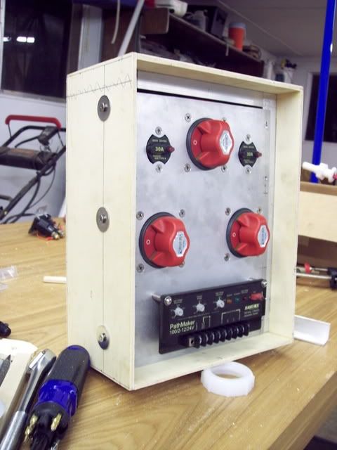
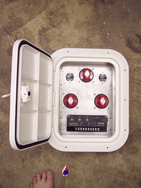
I have been moving along on the battery panel project I have been bragging about. I finally got the hatch I wanted for it and completed the enclosure. Next will be finishing paint and powdercoat.

panelside2.jpg


panelhatch2.jpg


panelenclosed2.jpg
 

roscoe

Supreme Mariner
Joined
Oct 30, 2002
Messages
21,800
Re: More Battery switch Panel Pics

Wow, looks very nice.
Well except for that crooked toe. d:)

Good job.
 

tashasdaddy

Honorary Moderator Emeritus
Joined
Nov 11, 2005
Messages
51,019
Re: More Battery switch Panel Pics

looks like you're doing it right.
 

cjames

Petty Officer 3rd Class
Joined
Mar 23, 2007
Messages
83
Re: More Battery switch Panel Pics

looks nice! is there a drawing of the wiring to go with it? hard to tell what youre doing with 3 switches, 2 fuses, and what is that, a charger, regulator? Im new here, so I guess if I look around a little more I'll find other related posts that explain all this.
 

drewpster

Commander
Joined
Oct 17, 2006
Messages
2,059
Re: More Battery switch Panel Pics

cjames here is the wiring I am doing in the enclosure. The two 30 amp breakers on the top left and right are the main breakers for the cabin. One will power the main fuse panel located in the cabin the other is a dedicated breaker for the macerator pump in the head. The small panel located at the bottom is the control panel for the ACR (automatic charging relay).

The two battery switches in the middle left and right are the main battery isolation switches, one house the other start. The battery switch in the middle at the top is a manual combine switch for the isolated battery banks. See diagram below:

relibattery.jpg


The system is designed to provide battery isolation between the house circuits (cabin, lights, accessories) and the start circuit (engine, starter, gauges, bilge). The auto relay closes when the engine is running to charge both batteries and opens to provide isolation when the engine is off. This means when the engine is off no power is drawn from the start battery. The two breakers are there because they will be close to the power source and give easy access to the breakers when the panel is installed. The third battery switch is there to provide a manual means of paralleling the batteries in case of ACR failure. It also can be used to route power from either battery to either system in case of battery failure. Its a good reliable system. I have not had a dead battery on board since I installed it. Before I built this box I had all the switches installed below decks. Since I am in the process of refinishing my boat I thought it would be a good time to build the panel and get it installed in the cockpit where it belongs.
 

cjames

Petty Officer 3rd Class
Joined
Mar 23, 2007
Messages
83
Re: More Battery switch Panel Pics

Thanks for explaning. Looks like a very solid system, beats mine for sure. The switch is a 1/2/both/off and its under the engine cover, making it a real pain. That may be next years project. This winter was new house wiring and DC fuse panel, that all started with the instalation of some new nav electronics, and snowballed into a garbage can full of wire and many hours re-doing things my way. cleaned up some of the engine wiring, but again, thats another project in itself, and theres really nothing all that wrong with the factory engine harness.

Its taken me a while to warm up to the ACR's, but more and more of my friends are using them, so I guess its time I give in. Good luck!
 

drewpster

Commander
Joined
Oct 17, 2006
Messages
2,059
Re: More Battery switch Panel Pics

My ACR is an older design. I plan to use a larger alternator so I wanted some amp capacity built into the ACR. It also offers the benefit of having very little voltage drop across the switch.
 
Top