Need help with boat gages

Silvertip

Supreme Mariner
Joined
Sep 22, 2003
Messages
28,771
Re: Need help with boat gages

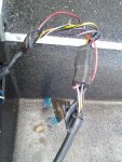
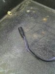
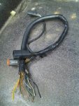
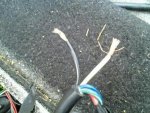
If you follow what daisy chaining is and have done what we told you then there is nothing else left to deal with. So I will try one more time. The purple wire from the control box goes to the +12 volt terminal (the "I" terminal) on the first gauge in the string. It doesn't matter which one. Obviously the first gauge would be the one farthest to the right (closest to the control box) is it not? You then run a wire from that terminal to the +12 volt terminal on the next gauge, then the next. At the end of the line there will no more wires. The black wire goes to the ground terminal on the first gauge. Then that terminal gets jumpered to the next gauge, and the next and the next. What you did with the gauges internal light connection is puzzling but here is what needs to happen. That light circuit has nothing to do with the ENGINE harness because it is part of the BOAT harness. Daisy chain the light connection just like you did +12 volts and ground. The "L" connection on the first gauge gets connected to the NAV/ANCOR light switch. It connects to the NAV side of the switch -- not the power side or the lights in the gauges will be on all the time. Connect it to the side of the switch that turns on BOTH the bow and stern lights. At this point the only connections remaining are the FUEL SENDER, TEMP SENDER, TRIM SENDER, TACH SEND. Tach send ("S" terminal) gets the gray wire. If your engine doesn't have a TEMP SENDER (different from a TEMP SWITCH) then the temp gauge will not work. You need to verify if there is a temp "SENDER" on this engine. The wire is typically brown/tan. The FUEL SENDER wire is typically pink. All of those get connected to the "S" terminal of the applicable gauge. You also say you took pictures. So post them. At this point we are 19 posts into trying to help and we are no closer to a solution than when we started.
 

mav6759

Chief Petty Officer
Joined
Jun 25, 2007
Messages
489
Re: Need help with boat gages

All my gages are connected as you said, thats not the problem., Once all the gages are connect it leaves two wires as you can see in the pictures. These 2 wires run from the tilt/trim to the rear of the boat. They are not connect to nothing, therefore, there is no power going to the gages. Now, I found a 12v switch wire coming from the controls, that wire does nothing, I tried hooking right to the battery all that did is turn on the lights for the gages and made the gages act crazy. I have 6 wires coming out of my control box (as you see in the pictures) to a plug, my problem is powering the gages, not connecting the gages in the daisy chain, they are already connected, it geting power to them to operate the gages. As you will see in the pictures, 1 picture shows the Black and white/tan wire that leads from the tilt/trim to the rear of the motor. 1 picture shows the wires coming from the control box which has 6 wires, that plugs into a 6 wire harness. and the other pictures are pictures of the control box and harness going to the motor. All I need to know is how these gages are powered. Because I can't power them through the controls, tried that, I can't power them right to the battery, tried that.. I can't power them through the fuse box tried that. All I have is these two wires as you see them in the pictures.
 

Attachments

  • IMG_20120107_151439.jpg
    IMG_20120107_151439.jpg
    152.4 KB · Views: 0
  • PART_1325986098518.jpeg
    PART_1325986098518.jpeg
    13.8 KB · Views: 0
  • PART_1325986119520.jpeg
    PART_1325986119520.jpeg
    14.7 KB · Views: 0
  • PART_1326038864638.jpg
    PART_1326038864638.jpg
    27.5 KB · Views: 0
  • PART_1326038969669.jpeg
    PART_1326038969669.jpeg
    14.6 KB · Views: 0

mav6759

Chief Petty Officer
Joined
Jun 25, 2007
Messages
489
Re: Need help with boat gages

These are the only 6 wires that I have to choose from coming from the controls, to the engine harness, which has the same wires. Now if I'm missing some wires or have the wrong controls that a different story. I was told that these controls were for a 95 engine and higher. I asumed that this set of OMC control had all the wires I needed.

IDENTIFIER FUNCTION WIRE COLOR CODE CONNECTS TO
B BATTERY Red with Violet stripe Battery positive via fuse
A or I ACCESSORY or IGNITION Violet Accessory loads; engine ignition
S START Yellow with Red stripe Engine starter solenoid coil
C CHOKE Violet with White stripe Engine primer solenoid coil
M (raised) MAGNETO Black with Yellow stripe Engine ignition kill circuit
M MAGNETO Black Engine chassis or battery negative
 

mav6759

Chief Petty Officer
Joined
Jun 25, 2007
Messages
489
Re: Need help with boat gages

Ok I did some cheching, the two wires shown in the pictures (Black and white with tan) are already live, both have power to them. Now I have to figure out where they go. Need Help
 

mav6759

Chief Petty Officer
Joined
Jun 25, 2007
Messages
489
Re: Need help with boat gages

Ok doing a little more research, the wire coming from the gages are being powered through the fuse box and not the switched wire. So at this point I have to disconnect all the gages from the fuse box, run a wire from the switched wire and see if it works. Any help would be great.
 

NYBo

Admiral
Joined
Oct 23, 2008
Messages
7,107
Re: Need help with boat gages

I think you're almost there. Connect to the proper terminal on the ignition switch. You're going to have to trace those "extra" wires to their other ends.

BTW, not gainsay Silvertip or confuse things, some boats come with the instrument lights also wired through the same terminal on the ignition switch as the gauges so they are on whenever the ignition is on. That's how my boat was wired.
 

mav6759

Chief Petty Officer
Joined
Jun 25, 2007
Messages
489
Re: Need help with boat gages

More research done, Apparently, the last owner of the boat did not wire the gauges through the key switch, What I found out is the gauges were wired to a toogle switch for power. so when he want to use the gauges he would flip the toogle switch. Now really confused,,,HELP
 

Silvertip

Supreme Mariner
Joined
Sep 22, 2003
Messages
28,771
Re: Need help with boat gages

I think you're almost there. Connect to the proper terminal on the ignition switch. You're going to have to trace those "extra" wires to their other ends.

BTW, not gainsay Silvertip or confuse things, some boats come with the instrument lights also wired through the same terminal on the ignition switch as the gauges so they are on whenever the ignition is on. That's how my boat was wired.

Understand that. No disagreement. Just don't understand the logic for having instrument lights on in broad daylight hence my recommendation for the NAV side of the light switch. There is also no reason to have the instrument lights on when at anchor so again -- have them on the NAV side of the switch so they are on only when 1) at night and 2) underway.
 

Silvertip

Supreme Mariner
Joined
Sep 22, 2003
Messages
28,771
Re: Need help with boat gages

See what I mean about not knowing what the previous owner did? What logic is there in having to flip a switch to have functioning gauges when they only need to be active when the key is on. It is just too simple but folks tend to get switch happen and think they need a separate switch for everything on the boat.
 

mav6759

Chief Petty Officer
Joined
Jun 25, 2007
Messages
489
Re: Need help with boat gages

I think right now I just want the fuel gauge to work, if I can get the fuel gauge working that would be great. I went this long without the tilt/trim, tach, and temp gauges. from what I understnad all I have to do is find the sending unit wire add power and ground and should be ok.
 

Silvertip

Supreme Mariner
Joined
Sep 22, 2003
Messages
28,771
Re: Need help with boat gages

If you use the SEARCH feature using Fuel Gauge as the keyword you would find 60 or 70 posts on how to troubleshoot that system. But siince you didn't, here is the diagram again. Just so you understand -- the pink wire DOES NOT get +12 volts on it. That wire goes to the "S" terminal on the gauge. The metal shell of the sending unit must be grounded as well as the gauge for this system to work. You keep saying the gauges have +12 volts and ground daisy chained properly but seem willing to give up on one last connection. If what you say is true, then all the tach needs is the gray wire connected to the "S" terminal. The speedo is not electrically powered except for the internal light so all that needs is the plastic tube connected to the tach and to the pitot on the engine or a separate pitot mounted to the stern of the boat. And by all means, get power for the gauges from the ignition switch "A" terminal.

Gauge-SenderWiring.jpg
 

mav6759

Chief Petty Officer
Joined
Jun 25, 2007
Messages
489
Re: Need help with boat gages

Ok I looked at the diagram and followed it to a T.. But I am still having issues. At the moment I am connecting the fuel gauge. On the back of the fuel gauge I have the following.. SNDR - Which I believe is the sender, GRND - Which I believe is for ground, POS - Which I believe is for Switch. And I also have a single wire just for the light in the gauge. OK, the way I have it connected is I have two wires Red and Black running from the gauge to the tank. The red wire I connected to the Postive side of the float on top the tank, the other end of the red wire I connected to the SNDR on the gauge, the black wire I connected to the GRND of the gauge and then jumped it to the negitvie side on the fuse box. (to have a ground at the float and gauge.) on the POS of the gauge I connected to the switch from the controls. My problem is the way I have it connected, the gauge jumps the full and stays there. I have the float out of the tank and moving the float by hand, the needle says on full unit I disconnected either the ground or cut off the switch. Is this a gauge issue or do I have something backwards.
 

Bondo

Moderator
Staff member
Joined
Apr 17, 2002
Messages
71,357
Re: Need help with boat gages

Ok I looked at the diagram and followed it to a T.. But I am still having issues. At the moment I am connecting the fuel gauge. On the back of the fuel gauge I have the following.. SNDR - Which I believe is the sender, GRND - Which I believe is for ground, POS - Which I believe is for Switch. And I also have a single wire just for the light in the gauge. OK, the way I have it connected is I have two wires Red and Black running from the gauge to the tank. The red wire I connected to the Postive side of the float on top the tank, the other end of the red wire I connected to the SNDR on the gauge, the black wire I connected to the GRND of the gauge and then jumped it to the negitvie side on the fuse box. (to have a ground at the float and gauge.) on the POS of the gauge I connected to the switch from the controls. My problem is the way I have it connected, the gauge jumps the full and stays there. I have the float out of the tank and moving the float by hand, the needle says on full unit I disconnected either the ground or cut off the switch. Is this a gauge issue or do I have something backwards.

Ayuh,... That's because, You don't have it wired Anywhere Near the diagram Silvertip posted...

The Gauge is grounded at the dash, the Tank is bonded/ grounded to the motor's block, or the (-) at the battery....

Yer runnin' 2 wires from the gauge... it should be 1 pink wire...
 

mav6759

Chief Petty Officer
Joined
Jun 25, 2007
Messages
489
Re: Need help with boat gages

I connected the gauge according the the diagram. I connected the ground from the sender right to the battery, connected the pink or (red) wire right to the sender. Under the dash, the gauge is grounded at the fuse box, the other end of the pink or (red) wire to the sender of the gauge. And powered through the switch. Just like the diagram, But I'm still read full when all connected.
 

Silvertip

Supreme Mariner
Joined
Sep 22, 2003
Messages
28,771
Re: Need help with boat gages

That's not what you said you did in the earlier post. You said you had two wires (red and black) running from the gauge to the tank. You only need one and it should be pink (but since electricity doesn't care what color the wire is it's ok to use another color). Connect from the SNDR on the gauge and the other end to the threaded terminal on the sender at the tank. Follow the diagram -- one wire at a time. This ain't rocket science. A fuel gauge pegs full when the GND terminal is jumpered to the SENDER terminal. So you either have it screwed up at the gauge or the sender. I can't make that diagram any simpler.
 

mav6759

Chief Petty Officer
Joined
Jun 25, 2007
Messages
489
Re: Need help with boat gages

Ok I pulled all that wire out and ran and new wire. I think the Red wire had faded over 32 years and it looks Pink. But now I do have red, I followed the diagram to a T, I had it connected both way to see if it would work and it didn't. Instead of running the ground wire back under the dash where it was, I connected it right to the battery (negitive). I ran the new red wire under the dash to the gauge SNDR and the other end to the sender (float). So I grounded the sende or float (as shown in the diagram) to the battery. Then I grounded the gauge at the GRND under the dash to the negitive side of the fuse box, and connected the switch the POS. The gauge still reading full. Now at this point either I have a bad 30 year old gauge or the float in the used tank I just got is bad. Is there a way to determine.
 

Silvertip

Supreme Mariner
Joined
Sep 22, 2003
Messages
28,771
Re: Need help with boat gages

Back at the tank -- what do you have the ground wire connected to? It must be connected to the metal shell of the sender, not the threaded post. Only the pink (red) wire goes on the threaded post. You need to make sure ground on the fuse panel is actually grounded back to the negative post on the battery. You should have a red wire running from the POS terminal on the battery to the fuse panel. There should also be a black wire running from the NEG post on the battery to the ground terminal on the fuse panel.
 

mav6759

Chief Petty Officer
Joined
Jun 25, 2007
Messages
489
Re: Need help with boat gages

Back at the tank there are two wires, pink (red) and black. The pink (red) is connected the threaded post on the sender, and the black is connected to metal shell on the sender. The black is then grounded to the battery. The other end of the pink (red) wire is under the dash connected to the SNDER of the gauge. And the switch is connected to the POS of the gauge. My fuse box is grounded at the battery. and another ground wire from the fuse box to the GRND of the gauge.
 

Silvertip

Supreme Mariner
Joined
Sep 22, 2003
Messages
28,771
Re: Need help with boat gages

1) Disconnect the pink wire at the fuel tank sender.
2) Does the fuel gauge now read zero or is it still pegged. (Yes or No)
3) If yes the pink wire is either shorted to the GRND terminal at the gauge or it is shorted to ground somewhere between the tank and the gauge.
4) If the answer to #2 is NO - then the problem is at the tank. Either the threaded post is shorted to the metal shell of sender or there is an internal problem with the sender. Only an ohm meter will help you determine if that's the case. Do not replace the sender until you prove it's actually bad. A fuel sender will measure 33 ohms full, 109 ohms half full and 240 ohms empty.
 
Top