Power tilt and trim Valve Assembly repair HELP PLEASE

Status
Not open for further replies.

northern

Recruit
Joined
Jun 7, 2007
Messages
5
Mercruiser 470

Tilt and Trim Motor Help Please
$_57.jpg

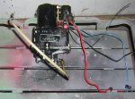
Tilt and Trim was not working sounded like a broken gear in up or down attempt, took unit apart noticed the shaft from the motor did not fit into the little round gear inside the Gear Assembly that circulates the fluid.

WITHOUT
thinking i took the Gear assembly apart and bearings fell out from locations inside, which is why i am here now i have the service manual and cannot find any information as to location of these bearings and springs from within.

I have included pictures, hope someone has worked on them or came across the same problem and managed to find a fix and locations of where they go.

IMG_20140504_125011.jpg
On a further note the little Gear did not fit properly but i have managed to fix that and now seats perfectly on the shaft, shown with gear locations installed.

IMG_20140504_123545.jpg

Just a further note if you can see by the pictures the springs are all different diameter and length
IMG_20140504_123412.jpg

Screw Holes.jpg


Any help would be appreciated and if i need to add additional information please tell me.

Thank you in advance
 

dubs283

Vice Admiral
Joined
Jul 27, 2005
Messages
5,333
Re: Power tilt and trim Valve Assembly repair HELP PLEASE

what manual are you using??
 

northern

Recruit
Joined
Jun 7, 2007
Messages
5
Re: Power tilt and trim Valve Assembly repair HELP PLEASE

IMG_20140504_141611.jpg

CLYMER Mercruiser Shop Manual
 

thumpar

Admiral
Joined
Jun 21, 2007
Messages
6,138
Re: Power tilt and trim Valve Assembly repair HELP PLEASE

You can use that as a knee pad. Look in the Adults Only sicky for the factory manual.
 

Bt Doctur

Supreme Mariner
Joined
Aug 29, 2004
Messages
19,346
Re: Power tilt and trim Valve Assembly repair HELP PLEASE

I have one .pm if interested. Been doing merc for quite some time now and have never seen a diagram of the pump body
 

bently

Petty Officer 1st Class
Joined
May 24, 2009
Messages
202
Re: Power tilt and trim Valve Assembly repair HELP PLEASE

I just did what you are attempting to do but I forgot to take pictures, I know this is no help now. The screws above where the springs and ball bearings go can be backed off and allow for easier re-assembly. Just count the turns and adjust back so the tension holds enough pressure on the bearings. Not enough and you will be doing this all over again.
 

northern

Recruit
Joined
Jun 7, 2007
Messages
5
Re: Power tilt and trim Valve Assembly repair HELP PLEASE

Problem is I don't even know where to start because like I said once the bearings fell out I simply stopped paying attention and didn't take note of where everything fell out from.
I just did what you are attempting to do but I forgot to take pictures, I know this is no help now. The screws above where the springs and ball bearings go can be backed off and allow for easier re-assembly. Just count the turns and adjust back so the tension holds enough pressure on the bearings. Not enough and you will be doing this all over again.
 

bently

Petty Officer 1st Class
Joined
May 24, 2009
Messages
202
Re: Power tilt and trim Valve Assembly repair HELP PLEASE

I believe the two smaller springs and ball bearings go above the two inserts that look alike. The large spring fits over the part that looks like a float needle and the large ball bearing goes in the slot above and to the right of the two gears. That is what my memory is telling me, I hope this helps.
 

Nidza

Recruit
Joined
May 26, 2017
Messages
1
Hello,

I know this is an old thread, but I want to write it here so it is all written in the same thread and at one place and I do also need a last bit of information if anybody knows the correct answer. I have this same Prestolite trim pump (only without control valve on the bottom of the pump, but the valve body is the exactly the same) and have the same problem to assemble it, but I do know where each chekball goes, but I am not sure of two smaller springs which can interchange places what is the correct place for each. Here are the photos, so it will be more clear.

On the first photo, all removable parts of chekball valves that should be present are shown. Except these parts, there are also three more removable parts, two gears shown on the second photo and "connector" which connects the gear to the electric motor shaft. I used the photo from the thread, so there are shown two small checkballs, but there are three small checkballs.


On the second photo is shown where each part goes. I have concluded this by watching hydraulic circuit scheme from the manual, photos from the net, and comparing how it works and by remembering some positions before disassembling the pump.


Now the main last question is: There are two smaller springs, which are of similar diameter, but not of same length, does anybody know which one goes above the smaller checkball and which one goes above the "squared "floater"? I would appreciate this answer as soon as possible. If I do not get the answer soon, I will first try longer spring above "floater" and shorter spring above the small ball. If leg will not work OK, I will interchange it. But, even the system working does not mean that it is correct, since the question is which one of these two should be for higher pressure protection (floater or chekball) since the one that should ave bigger pressure should probably have longer spring. One of these two releases pressure if the drive is fully up and the pump is still pumping and the other if the pump is stopped and the up pressure is too high (I understood this last one like if you hit something with the drive, but I could be worng). You can see more explanation of these valves in this document (see hydraulic description for up and down):

https://web.statler.wvu.edu/~mathews/boat/pdf/manual/Chapter Eighteen.PDF

Bently, your not remembering correct because the big spring can't go over the "floater" since the spring holes define what size of spring can be put inside. The hole for the spring above floater is for one of smaller springs.

Thank you in advance for your answer.

Best regards,
Nidza

I could not upload photos, it says "You are not authorized to create or remove attachments." Anyway, here is the explanation in words which goes where. Squared floater is shown on the picture in post #1 where it goes (in one shiny insert there is squared object with smal circle pin). Let's watch only the last photo from the post #1. The big chekball goes in the middle hole on the right side of two gears, just next to the gears (when assembled it will be matched to the straight slot with the hole). In the big hole on the right side from the big checkball hole goes the big spring and on top of spring goes the small checkball (when assembled it will matched to the individual/sole shiny insert). In the hole top left which is paird with squared "floater" inside one insert goes one of two smaller springs. In the hole on the left side which is paired with the second insert closer to gears goes the second smaller spring and small chekball above the spring. In the hole on the left which is in the middle between two screw holes and whicih is paired with curved slot with hole, goes small checkball. I hope it will be understandable only with text. The question stays, which of smaller springs go into which hole, is the longer small sping goes with the squared "floater" or with the small chekball?
 
Status
Not open for further replies.
Top