BB63QM
Petty Officer 3rd Class
- Joined
- Aug 4, 2023
- Messages
- 79
I am converting from manual trim assist to power trim. I have managed to find all the OEM parts (pistons, brackets, hoses, pump, 3-button, wire run, limit switch, etc), but am lacking a diagram or better yet, a set of pictures, that shows how the wiring hooks up.
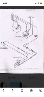
Specifically and for instance (there may be more), there is a 90A fuse in the parts diagram, but it is not shown on the wiring diagrams I have (attached), at least not force single-solenoid model (unless the “coil” notation is electro-see for fuse…see attached…and even then I’m confused).
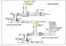
In the twin solenoid model (see diagram), the 90a fuse bolts to the positive terminal on the (starter) solenoid and then to the positive lead from battery. This makes good sense, so I assume that this is correct, but I have yet to find anything that confirms.
Also, in the single solenoid diagram, there is a terminal block bisecting the green wire…is that to be somewhere on the pump unit, or somewhere else?
Thanks for your help.
Gary
Specifically and for instance (there may be more), there is a 90A fuse in the parts diagram, but it is not shown on the wiring diagrams I have (attached), at least not force single-solenoid model (unless the “coil” notation is electro-see for fuse…see attached…and even then I’m confused).
In the twin solenoid model (see diagram), the 90a fuse bolts to the positive terminal on the (starter) solenoid and then to the positive lead from battery. This makes good sense, so I assume that this is correct, but I have yet to find anything that confirms.
Also, in the single solenoid diagram, there is a terminal block bisecting the green wire…is that to be somewhere on the pump unit, or somewhere else?
Thanks for your help.
Gary