Project Fishtoon

Status
Not open for further replies.

-dirt-

Seaman Apprentice
Joined
Jun 11, 2012
Messages
32
Re: Project Fishtoon

Thanks as always for this info.

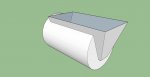
I'm really struggling with a transom section design that I think will withstand the weight of my Honda (487 lbs dry). If I understand you correctly, I think you are recommending a design similar to below but with additional 1/2" thick plates in lieu of the rectangle tube:

25inmotormount2.JPG.w560h420.jpg

My main concern lies with tying the new transom tube section to the "old" unmodified tube. I'm wondering if a design similar to yours with a beefed up transom, as discussed (1/2" plate with square tube), as well as an internal square tube frame that runs from the transom to the untouched center pontoon.

With this design, the transom section would be connected to the old, long tube via 1) the internal frame, 2) the welded circumference where the two tubes meets, and 3) any strakes, top braces, or other horizontal additional framing added that overlays both the old and new tubes.

I realize that I'm junking up your thread with my ideas, so I'll start a new thread of my own if you promise to subscribe to it and help out when possible! :) Thanks!
 

BrianMc

Petty Officer 2nd Class
Joined
Oct 2, 2010
Messages
177
Awe, that don't bother me. It's a build thread and your building. ;)

That design will work if the bulkhead ahead of the transom is like a 1/4" plate. The only thing I would add is a gusset on each side plate. How long is your main tube,and how long will the add-on be?

The forces at work are pulling on the top of the JP,and pushing in on the bottom. Problem is the JP only reaches half way down the transom,which places a lot of force in the center of the plate. That's why mine started to bow there. I needed more beef to bridge from top to bottom. The tubing or channel like in your photo strengthens it side to side,plus stiffens up the area your bolts run through. Still need the strength vertically though or the bottom channel will wrinkle the side of the tube as it pushes forward.

A 1/2" plate would spread forces evenly around the perimeter of the tube. But think a little more reinforcement is still needed. You need to transfer more of the force in the center of your plate to the bottom of your tube. You can run the top sq. tubing side to side. Then run two verticals down to the bottom picking up the bottom mounting bolts. Since the strake area is the stoutest, I'd aim them near there.
 

Attachments

  • IMG_20110702_140345b.jpg
    IMG_20110702_140345b.jpg
    65 KB · Views: 0
Last edited by a moderator:

BrianMc

Petty Officer 2nd Class
Joined
Oct 2, 2010
Messages
177
You know, a modified version of that photo you posted could be a handy way to make a transom tube. Make a trapezoid box that would drop in from the top. Let it run through the end cap,then weld it all the way around. Hmmm....
 
Last edited by a moderator:

-dirt-

Seaman Apprentice
Joined
Jun 11, 2012
Messages
32
Re: Project Fishtoon

How long is your main tube,and how long will the add-on be?

I picked up this beauty for a steal last week. 00v0v_8AT4IIqY8zX_600x450.jpg It has slightly shorter tubes than mine -- 23' or so, I believe. Same diameter.

I was thinking maybe a 24" transom section...haven't put the pen to paper on that. I've been planning to keep the current endcap on the full length pontoon and building onto the end of that. It would pain me to cut off a non-leaking endcap to replace with a 1/4" plate, but I could see where that would beef up the back end even more. Not ruling this out as an option

I was originally thinking of going with a design like yours (similar style attached): ty_pics_3_Medium.jpg with an internal frame for added strength: 20140306_090403.jpg

But the "box style" looks easier to fabricate and possibly just as stout. What did you mean when you said "let it run through the endcap"? With that style, I suppose it would have to be self-bailing with some drain holes, or either add a top piece with a hatch like yours.

Here's the site I found the "box style" picture: Products List
 
Last edited:

BrianMc

Petty Officer 2nd Class
Joined
Oct 2, 2010
Messages
177
Let the box run through the end cap of the add-on,then weld all the way around it. The transom plate would be strong like this.

I agree with leaving the main factory tube intact. That's what I done.​
 

Attachments

  • transombox.jpg
    transombox.jpg
    96.7 KB · Views: 0
Last edited by a moderator:

-dirt-

Seaman Apprentice
Joined
Jun 11, 2012
Messages
32
Re: Project Fishtoon

Ok I'm following you now. That design looks simple enough to fab. Would you think a bottom plate would be needed? also is the far left plate (near the end cap of the long tube) needed, or could the two side plates of the box just weld directly to the factory endcap? Lastly it would be easier for me to figure the measurements if the sides are not slanted. Slanted looks cooler but does it add any strength?
 

BrianMc

Petty Officer 2nd Class
Joined
Oct 2, 2010
Messages
177
This is sort of a concept,so bare with me. I don't want to re-invent the wheel,but what I'm seeing should work. When I get a chance I'll draw it up a little better for you. I'll be away tomorrow,but will try to get to it this weekend.

You won't be able to just weld the side plates to the cap. The 150 would crush the factory cap. Yes for this design to work the bottom plate would need to be there. In fact there would need to be something on top as well to stiffen the side plates there. Thinking 1/4" plate would be enough,with some channel or tubing at the transom. I would use the wedge shape for several reasons. It will make a stronger box,and the smaller the transom plate the stiffer it'll be. Another big reason is it'll be easier to get a tight fit dropping a wedge into the cut-out. Trim a lil here and there until it settles in for a tight fit. Make the box extra tall,when it's in place trace around the tube/box joint,pull it back out,and cut off the excess before welding it in. The mounting bolts are already in a wedge shape,so make it 3 or 4 inches wider than the bolt pattern.

The box itself would be stout. In order for the transom to move it'll have to move the whole box. With it welded all the way around it would have to fold the tube to move. Don't let the shape scare you. Could always make templates out of cardboard to figure it out. If you don't feel comfortable with the design,you still have plan A.
 
Last edited by a moderator:

BrianMc

Petty Officer 2nd Class
Joined
Oct 2, 2010
Messages
177
dirt, If it makes things simpler a square box will work using a thicker mounting plate. Sides,bottom,and top can be 1/4". You still have the transom angle to deal with,but that's not too tough. It could be built something like this
 

Attachments

  • transombox3f.jpg
    transombox3f.jpg
    109.2 KB · Views: 0
  • transombox3c.jpg
    transombox3c.jpg
    93.4 KB · Views: 0
Last edited by a moderator:

-dirt-

Seaman Apprentice
Joined
Jun 11, 2012
Messages
32
Re: Project Fishtoon

That looks really good. Is that using a 22" diameter tube? I'm guessing that about a 12" tall transom?

My only concern with that design would be the strength of the remaining portion of the factory endcap, since it seems there will be a lot of downward pressure from the transom mount plate onto the remaining half circle piece...

Would a taller box be just a strong, so that the bottom of the box would rest on the floor of the tube? A c-channel could be welded face down onto the floor of the tube to give the box something to be welded to.

What would the dimensions of #2 here need to be?: 20140311_142315.jpg

TRANSOM BOX

Here is what I'm looking at for the transom box, if I'm following you correctly:

  • 1/4" plate for all sides (left, right, top, bottom, and front)
  • 1/2" plate for rear piece
  • reinforcing c-channels -- either two horizontal channels like post #90 OR one horiz. and two slanted vertical like post #84
 
Last edited:

BrianMc

Petty Officer 2nd Class
Joined
Oct 2, 2010
Messages
177
The weight won't be sitting only on the remaining portion of the end cap,it's also hanging off the sides of the end cap and the top of the tube. I should have done this with mine. I've seen first hand the stresses involved. It's trying to pull the top of the plate out,and shove the bottom in. That torque is what the box will help. It will have to move as one. It can't go down without folding the tube,and it can't push in at the bottom without ripping it out the top of the tube. With just a transom plate welded on the end of the tube the most stress on the weld is at the top of the plate. That's why I used the turnbuckles.

If it helps to sleep at night you could tack weld some patches on the inside over the strake area of the tube,then build up off of those with supports. The hardest part of this will be cutting the opening in the tube and cap. I only drew 6" of tube behind the box,but think 12" would be better so the frame above can better tie the two sections together.

What dia. will your center tube be?


Yes, I think your list will work fine,and horizontal channel will be plenty on that small of a plate. I was looking at a plate 15"-16" wide and 12"-13" tall.

Something else that would be cool with this setup is you could tie the two drain plug ports together to drain the main tube. The small transom section on mine I use a small auto bilge pump,but I have no way to drain the main tube if it takes on any water​
 

Attachments

  • cutout.jpg
    cutout.jpg
    109.8 KB · Views: 0
  • cutout2.jpg
    cutout2.jpg
    128.3 KB · Views: 0
Last edited by a moderator:

-dirt-

Seaman Apprentice
Joined
Jun 11, 2012
Messages
32
Re: Project Fishtoon

The tube diameter is ~22". My motor has a 25" shaft, so it will need a 24" or so mounting height. So top of transom will need to be above the tube, if I'm thinking about this right...

What did you mean by tying the drain plugs together?
 

BrianMc

Petty Officer 2nd Class
Joined
Oct 2, 2010
Messages
177
That sounds about right for a typical height,mine is 19". Are you going to use a JP,and or hydr. steering?​
If your leaving the main tube intact and use the cap end of the second tube for the add-on,you'll have a drain plug on both caps. Connect the two together with a hose,so you can drain the main tube through the plug in the add-on section.​
 
Last edited by a moderator:

-dirt-

Seaman Apprentice
Joined
Jun 11, 2012
Messages
32
Re: Project Fishtoon

I already have Seastar hydro steering. I know a jackplate would be useful, but I may forego that additional cost now -- especially if I can get the transom height dialed in where on is not absolutely required for normal operation. I'm sure one would be great though for varying loads on the boat...

I got you now with the drains. (My old/base pontoons does not have drains in the bottoms just vents at the top, but the new ones do.). Are you thinking a barbed fitting screwed into the drain hole and then a hose ran to the rearmost endcap?
 
Last edited:

BrianMc

Petty Officer 2nd Class
Joined
Oct 2, 2010
Messages
177
Yeah, was thinking hosebarbs. Would have to dig through the fitting bins at the local hardware store,as the pipe threads in the rear cap would be backwards from the inside. Have to think on that one. There's probably fittings that can screw in from the outside with threads on the inside. One way would be using plastic airline with farrelled compression fittings.

My opinion with JP's on toons is go hydr. or not at all. At speed straked out toons ride higher and flatter than the typical mono hull. So the benefits come from being able to drop the motor which is the opposite on mono's. What I experience is somewhere around 5-10% in speed,or 2-4 mph. The other benefit is if you switch props often you can adjust for optimum height,as there can be 2"difference in where a given prop likes to run.​
Which brings me to another change I'd do next time. I say next time as I'd like to build a 22' fishtoon that'll run 60 mph with only a 200-225. I think it can be done. It'll take more bowlift and cleaner water coming off the transom tube. The last 3'-4' of the tubes need a pad incorporated into the bottom,with a tunnel on the center tube.​
 
Last edited by a moderator:

-dirt-

Seaman Apprentice
Joined
Jun 11, 2012
Messages
32
Hopefully about to start my pontoon makeover modeled after your design. Been planning this out for a couple years now and using what I have. Thanks for all your past info.

Another question for you: on the 2.5" outer rim of the floor frame, did you face the c-channel out or in? If faced in, did the 2" channel used for the floor joists fit inside the 2.5" channel and allow for welding along the top and bottom?

Free bump for an awesome build!
 

BrianMc

Petty Officer 2nd Class
Joined
Oct 2, 2010
Messages
177
Hey dirt, the 2.5" outer channel is turned out. The stringers butt into the backside of the 2.5",and are flush at the top. This way the 1/8" diamond plate is supported on all edges. Hope I get to see it when your done.
 
Last edited by a moderator:

-dirt-

Seaman Apprentice
Joined
Jun 11, 2012
Messages
32
Hey dirt, the 2.5" outer channel is turned out. The stringers butt into the backside of the 2.5",and are flush at the top. This way the 1/8" diamond plate is supported on all edges. Hope I get to see it when your done.


Thanks so much! I'll start a build thread for mine when I actually start doing notable work on mine. Been piddling with it so far. I have bolted up a 2/3 length toon in the middle front, just before the motor pod, as a temporary thing for more flotation. Probably stripping it all the way down next week though!! :/

One further question: was there a reason you used a taller side/rim c-channel, instead of more 2" stuff?
 

BrianMc

Petty Officer 2nd Class
Joined
Oct 2, 2010
Messages
177
Used the 2 1/2" rim for strength to extend the deck and to help carry all the added stringers. The older outer tubes had M-brackets spaced too far apart,as their wimpy frame had stringers spaced anywhere from 19"-24" apart. So the outer frame carries the added stringers that land between the brackets,plus those up front counter levered off of the longer center tube.

A 2" outer will be plenty if your not doing all of that. Although I'd recommend adding any extra stringers you might need in the future now while you have it open.​
 
Last edited by a moderator:

-dirt-

Seaman Apprentice
Joined
Jun 11, 2012
Messages
32
Yes, I'll be making a sub-frame for the floor like yours with a rim, as my tubes also only have brackets every 24".

Dumb question alert: is the 2.5" channel stronger than the 2" if they are the same gauge material? I'm not comprehending the need to step up in size for the rim...?

Speaking of the gauge material: did you use 6061 or 6063 stringers? In my research on this, the 6061 is roughly twice as strong as 6063, when comparing the same size stuff. However, the 6061 is called "structural channel" and has the shorter legs, whereas the 6063 (called "architectural channel") has the legs that are the same length as the height.

6061 structural 2" x 1" x .130" ($35 per 8' stick): http://www.metalsdepot.com/products/alum2.phtml?page=channel&LimAcc= &aident=

6063 architectural 2" x 2" x .250" ($82 per 8' stick): http://www.metalsdepot.com/products/alum2.phtml?page=6063 aluminum channel&LimAcc= &aident=

Would you think 6061 stringers sized .130 would be stout enough for the unsupported stringers that will get added in? My logic is if 6061 is twice as strong generally, then 6061 .130 should be about as strong as 6063 .250... It doesn't hurt that 6061 .130 is cheaper too.

For what its worth, my toon came with .125 c-channels (2" x 1.25") for most of the floor, with a couple .250 c-channels at the rear which the motor pod bolts too.

One more while I'm typing: did you use 3003 or 6061 for the floor? Again the 3003 is cheaper, but I'm afraid it might be too bright...

Thanks!
 

BrianMc

Petty Officer 2nd Class
Joined
Oct 2, 2010
Messages
177
Go with the cheaper 6061 channel for the added stringers,although it wouldn't hurt to pickup a few of the 1/4" thick sticks to add above the motor pod. Most of the strength of a channel is in the web. The taller it is the stronger it gets. If height is a factor,then web thickness adds to the strength. The two flanges help to keep the web vertical and from twisting (sorta like an I-beam does). There is some factor where the flanges do add strength,as under load the bottom flange has to stretch and the top flange compresses. The smaller flanges of the 6061 won't be much of a factor when the decking is screwed to the top flange. It can't twist,or lay over,so the web has to carry the weight. A 2" rim is plenty to carry the added stringers that land between the brackets.

I added to the length of my deck. It's counter levered 6" off the back,and 18" off the front ahead of the outer tube front brackets. The outer rim helps to carry the deck hanging out there. My deck is 102" x 24' above 24' outer tubes. I bought 2"x2"x3/16" 8' stringers that where actually almost 97". Then laid the 2 1/2" channel on it's side to get to the 102" width. The flange on it is 2",so turned that way it's not much stronger than a 2" channel turned right. I will add that my extended front deck does rest on the center tube spacers,so it's just counter levered at the corners.

I used the 3003 1/8" diamond decking. Plenty strong with my stringers on 12" centers. Yeah it was shiney at first,but untreated it dulls pretty quick. Don't even notice it now. My treated polished tubes are much brighter.
 
Last edited by a moderator:
Status
Not open for further replies.
Top