Questions following MPI Conversion

Swill008

Seaman
Joined
Oct 31, 2013
Messages
63


Reference Thread: http://forums.iboats.com/forum/engi...263-5-7-vortec-2bbl-to-350-mag-mpi-conversion

I posted to my Thread above and have waited for some responses. I guessing its too old and Ill let it sink into the forums. So Im posting a new thread and asking new questions.

Alright conversion is complete from 2 barrel to 350 MAG MPI is complete. I have three hours of run time on my setup - trying to break it in. I am using a scan tool (USB) and scanner pro.

Questions:

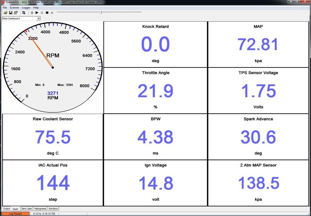
Under full load at 3000'ish RPMs the ECU is commanding 30deg spark advance, is this normal? I could not find the timing curve chart - maybe I overlooked it, I'm using manual #24.

I still need to put my timing light on it while operating it to see my actual max spark advance. I'll get that next run. I have a MEFI 3 ECU installed. I'm also running hyper pistons which actually recommend to decrease timing by - 2 degrees - if I understand correctly that means set base timing @ 6 deg instead of 8 deg.

My throttle body for the 1999-2000 MPI is the old school style - it has the stud in the center not the three studs on the outside diameter holding the flame arrestor. I have another old school throttle body, same style, that is in better shape (fresh water used - my installed was obliviously salt water). I would like to use the fresh water throttle body because of aesthetics but the stud is broken in the center. I've seen what appeared to me, to be a way to install with a clamp, not using a center stud. Can someone point me to where I can find the information or parts for using a clamp, if it's possible?

Another question: I have a 4 inch heat exchanger installed. The style installed has the raw water discharges coming from the left and right end caps to my manifolds. My port side manifold runs quite a bit warmer then my SB. I can keep my hand on it for over a min, so I don't believe it's detrimental. However, my ECU is installed on port side and heat kills electronics. In my system I do not have any type of diverter balls, my issue is flow diversion. Is there a way to use a diverter style in my setup or do I need to buy a new style heat exchanger to do what I'm wanting?

INFO/ISSUES FOR CONVERSION:


For anyone doing this conversion, you can not use the carburetor shift interrupt switch as designed in a MEFI system.

The carbureted style switch is normally open, which is what I had, it grounds out the negative coil wire to stumble the system. The MEFI system uses an normally closed switch that sends signal to the ECU to case stumble.

My fuel pressure under load is 32psi (cant remember exactly 32-34psi), right on for the older style MPI system. Newer style requires 43 psi, this was a correction to my first few posts about fuel pressure. For those that do not know there are two style regulators one is 32-34?psi the other is 43 psi.

I also had a problem on my first run with very high fuel pressure was around 60 psi, turned out to be the little filter between the pressure regulator and the cool fuel (old style) body. You'll see it after removal - the blockage causes a return side pressure increase which increases the overall pressure. I removed mine completely - I did not feel that I need it because I still have my Fuel Filter/Water Separator installed and that is where the return fuel goes back to.

Everything runs great, under load - but I get what feels like a small stumble around 1500-2000 rpm, I am thinking I have my plugs gaped incorrectly. I gaped at 45, I think they should have been 65 or so, I cant remember my plugs part number at the moment. Ill update when I have time to find it.

Ill be glad when I can get to WOT, right now I'm babying her.

Also side note it took me a year to complete this project and the first run I put her into the rocks in the river and destroyed the prop and done some damage to the transom area gel coat - I replaced the prop (no damage to the shaft) and did the gel coat repair to the transom. Basically life sucked for the first day - Karma I guess! Don't know who I pissed off!

She's back to normal now!

Thanks for reading.
 

achris

More fish than mountain goat
Joined
May 19, 2004
Messages
27,468
Question #1. The ECU determines advance based on engine speed, MAP and knock sensor feedback. It will advance the timing until it detects knock, then retard it 2 degrees. This is best power and economy. It does that check over 100 times per second.If you advance or retard the spark distributor it will not change the timing set by the ECU...

Question #2. Very little you can do about the water flow. The water will follow the path of least resistance, and it's quite normal for one side to be warmer than the other. Once you get a few revs up and have plenty of flow from the pickup pump, that should even it out...

Best I can do right now... Sounds like a nice conversion...

Chris......
 
Last edited:

Swill008

Seaman
Joined
Oct 31, 2013
Messages
63
Question #1. The ECU determines advance based on engine speed, MAP and knock sensor feedback. It will advance the timing until it detects knock, then retard it 2 degrees. This is best power and economy. It does that check over 100 times per second.If you advance or retard the spark distributor it will not change the timing set by the ECU...

I understand the commanded spark advance, however I was under the impression that commanded does not necessarily equal actual spark advance, based on where the base timing is set. So I thought for the sake of it I would check my total advance timing under load around 3500 rpm, But I haven't found the total spark advance I should be running at. Looking for the chart :( cant seem to find it in manual #24

If I understand correctly:

Base timing is set at 8deg BTDC reading the forums; if total advance supposed to be 35, I take 35 subtract base timing of 8 = that gives me: 27 ATDC deg total advance and I should see 27-25 ATDC total advance with my timing light. Am I understanding that correctly?

Question #2. Very little you can do about the water flow. The water will follow the path of least resistance, and it's quite normal for one side to be warmer than the other. Once you get a few revs up and have plenty of flow from the pickup pump, that should even it out...

Best I can do right now... Sounds like a nice conversion...

Chris......

Thanks for the response Chris, I think Ill just make some 1 or 2 inch standoffs for the Port Riser ECU mounting bracket - that way my ECU will not be as close to the manifold. This should allow enough airflow and hopefully save it from heat damage.

Any thoughts on the Flame Arrestor installation? As stated above mine is center bolted, can they be installed with a clamp - Factory clamped that is, I could always cut slits into the collar of the arrestor and use a clamp however, I want to want to do it the way the factory would.


Also here is the Donor ENG SN: 0M013927

1999 350 MPI MAG with MEFI 3 system, mated to an ALPHA 1, GEN 2 drive.
 
Last edited:

achris

More fish than mountain goat
Joined
May 19, 2004
Messages
27,468
They is no 'Base timing' on an MPI... The ECU determines timing, doesn't matter where you set the spark distributor, it takes its timing signals from the crank angle sensor, in the timing cover, and that is fixed.

Stand-offs for the ECU sound ok.

Can't help you with the flame arrester problem, sorry...
 

JustJason

Vice Admiral
Joined
Aug 27, 2007
Messages
5,321
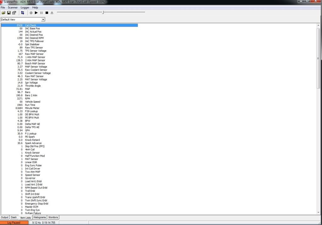
Part of what I see is your Map is screwy. That can mean you have a bad map, or you might have a non-sealing intake valve, or something else. But it probably just a map issue both your innie and your outie are no good.

At 3k rpms your map is reading 73 kpa, which is about 10psi, which is way to high for an engine turning that many rpms, you should be closer to 5 or 6 psi.

I'm not familiar with your software, but I'm assuming on the bottom right where it says atm map sensor that it means Atmospheric. It's reading 138 KPA, which is roughly 20 psi. . That's a good reading in you live on Venus. But here on earth atmospheric pressure is 14.6 psi at sea level on your average day. If your ECM thinks atmo is 20 psi it will never run correctly. That needs a looking at, and your fuel pressure should be cranked up to 40-45 psi for something like this.

As long as your software is accurate, and you can plumb in a basic vacuum gauge to double check it. Your Map is off 5 to 6 psi on both the maniolds pressure measurement, and also the atmosphereic measurement.
 
Last edited:

Fun Times

Moderator
Staff member
Joined
May 16, 2009
Messages
9,124
~~
There is no 'Base timing' on an MPI... The ECU determines timing, doesn't matter where you set the spark distributor, it takes its timing signals from the crank angle sensor, in the timing cover, and that is fixed.
Oops, Since he has a MEFI-3 system, he is able to set initial timing to what he want's (sort of speak). The MEFI 3's use a hall effect sensor under the distributor cap which is used as a timing reference. The ECM completely controls the timing.... kind of like the thunderbolt ignition control module does or the ignition coil driver (transistor) which was built into the EST ignition module used on the MEFI 1 and 2's is now just inside the MEFI-3 ECM. With these 3 models, the base timing has to be within specifications so the built in advance features inside the ECM's will work within normal known range.

To manage the timing and fuel, the ECM looks at all the other sensors. But just like the thunderbolt ignition system, if he set's the initial timing out of specifications, it should affect the total timing as well.
MEFI 4, 4B, 5 on up work different then 1 & 2 or 3. The 555 ECM changed as well.


Swill008, In service manual 24, Be sure to read all of section 5D for a better understanding. Page 5D- 20 & 21 will really help along with this that is not in the service manual.
(EFI engines with mercury marine thunderbolt V distributor and MEFI-3 ECM 1999 V6 and small block V8 engines: The ECM incorporates an integral ignition module (coil driver circuit). This is only used on the small block V6 & V8 models (except Scorpion models). A standard thunderbolt distributor and ignition coil are used, but the ECM controls ignition coil dwell and timing. This integral module is not used on big block models.)


I'm also with Jason, a lot (most) of your numbers above seem way off which will throw your timing numbers out of spec like you seem to be seeing. I believe I'm used to seeing the mid cruise RPM's in the upper 20's like your thinking you should be at.
Your serial number used to be for a Bravo drive, not an alpha. Since it's an Horizon engine model with closed cooling, are you running an engine mounted sea water pump? or using the impeller inside the alpha stern drive? Also does your thermostat housing look like this. http://www.ebay.com/itm/Housing-The...sed-Cooling-GM-Engines-861188A1-/230698096755


http://www.crowleymarine.com/search_...tring=0M013927
Service Literature for MERCRUISER 350 HORIZON BRAVO ENGINE ONLY 350 MAG BRAVO MPI


Here's the info about the clamping flame arrester.http://www.mercruiserparts.com/Show_...FLAME+ARRESTOR
 
Last edited:

Swill008

Seaman
Joined
Oct 31, 2013
Messages
63
Thanks gentlemen!

Fun Times,

I am using that thermostat housing that you linked to, I'm running closed cooling and a 160 thermostat. My temps do not go above 170deg. I'm using the alpha drive impeller housing for my closed cooling system, raw water cooling both my manifolds.

I'm at the basics for reading my ECU parameters.

Jason,

Thanks for helping me understand my data. I only have one map sensor and I do not have any o2 sensors. I believe that call that an open loop system? (Correct me if I'm wrong!) I do not understand how I could have two map readings if only one map sensor! Unless both are built into one. I'll change my map again to see if that changes my data. I also have another mefi 3 ECU, I'll swap that around and see if that changes things. All in all she's running very well (to me that is!), but I was thrown by the data as well! Didn't understand how my map could be so high, then again you don't know, what you don't know.

Sorry for the late reply I have been very busy with work! Time to get back on the boat. I'll plumb a vacuum gauge and check it out. I had my intake cut/hot tanked at the machine shop to correct for any warpage, also new 906 heads with stainless valves - 3 angle grind - but maybe I do have a vacuum leak - I also did not use the cheap plastic intake gaskets, I used the heavy duty ones from fel pro the 9800 I believe - metal imbedded with rubber.

I did change out my map sensor with automotive - I should use/check another map to make sure I didn't shoot myself in the foot. ( I have the little square one - not the large rectangular one ) Thanks for the information gentlemen! And also for the input! I'll try these suggestions and post another data log. If you guys have scanner pro I could email you my data log of my run, you can play it back and see what's happening.
 
Last edited:
Top