Rectifier/ Regulator test

eggage1

Cadet
Joined
Nov 7, 2010
Messages
19
Just want to verify that I am testing the regulator correctly.
Engine is a 1987 225HP Yamaha Excel XH.
I have a low battery problem in that the battery is always at about 12.5V even with the engine running.
I disconnected the rectifier/ regulator and tested as per my manual with an ohmeter.
It all checks OK except that I have continuity between the black and one of the green terminals with both polarities.

I'm thinking the unit is bad but I would like some thoughts before I plunk down for a new one.
Battery is new and fully charged.
Thank you.
 

Shermanator31660

Petty Officer 3rd Class
Joined
May 15, 2006
Messages
88
Re: Rectifier/ Regulator test

With the battery and everything else connected and your not getting a charge at the battery checked via a volt meter, go back and pull the two leads that come from the rectifier/regulator and use a volt meter to check there to see if there's power. Mine was not charging the battery properly from my kicker but the rectifier/regulator showed there was power there. Turned out that I had to run a separate ground wire from my kicker (from the block) directly to the negative terminal on the battery. I figured this out when I was hooking up the steering arm and I kept getting sparks between the arm and the kicker bracket where it hooked up to. New ground wire on and tons of charging now so, maybe your having a ground problem?? Sherm
 

eggage1

Cadet
Joined
Nov 7, 2010
Messages
19
Re: Rectifier/ Regulator test

Thank you for that info Sherm. I will try that but I'm thinking that the rectifier is bad because I tested it disconnected.
I just would like to verify that I tested it properly.

Mike
 

99yam40

Fleet Admiral
Joined
Sep 7, 2008
Messages
9,127
Re: Rectifier/ Regulator test

check voltage from lighting coil to make sure it meets minimum spec in manual.
If it does and voltage out of R R is not in spec then it is bad
 

eggage1

Cadet
Joined
Nov 7, 2010
Messages
19
Re: Rectifier/ Regulator test

99yam. My manual (Clymer) just gives resistance readings for the coils. No voltage readings. The resistance measures correctly.
To check the voltage would you remove the leads from the voltage regulator going to the coils and then run the engine while taking a reading?
 

99yam40

Fleet Admiral
Joined
Sep 7, 2008
Messages
9,127
Re: Rectifier/ Regulator test

There should be Peak voltage specs for cranking and at different RPMs
My Manual for my C40 shows measuring hooked up to start with and then if too low disconnect and remeasure.
If reading comes up replace R R, if too low still replace lighting coil
 

eggage1

Cadet
Joined
Nov 7, 2010
Messages
19
Re: Rectifier/ Regulator test

Thanks 99yam. I will keep looking to see if I can find those specs. In the meantime though I shouldn't read continuity both ways on black and green at the regulator with all wires disconnected should I?
Sherm: Checked the grounding. All good.
 

boscoe99

Commander
Joined
Aug 22, 2013
Messages
2,058
Re: Rectifier/ Regulator test

Voltage output specs are not given for a 1987 Excel.

Sounds like your lighting coil is shorted to ground, in which case there won't be any output.
 

boscoe99

Commander
Joined
Aug 22, 2013
Messages
2,058
Re: Rectifier/ Regulator test

Here is a diagram from a later model motor that provides output specifications for a single phase lighting coil. Your coil output should be more or less the same. It will probably be less given that the specs I am providing are from a later model, which theoretically should have better output. Who knows.

Start and run the motor while measure peak voltage output between the two green wires. I am guessing you won't see any voltage given your statement that one of the green wires is grounded.

If you have voltage output from the lighting coil, but no output from the rectifier/regulator, then the R/R is kaput.


eggage1

Cadet
Joined
Nov 7, 2010
Messages
19
Re: Rectifier/ Regulator test

Thanks Boscoe99.
I'm thinking I didn't explain correctly though. I took reading on the rectifier/regulator itself with all wires disconnected.
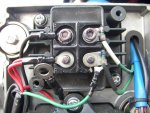
There are four posts on the RR. They are labeled "B" "R" "G" and the fourth has no designation.
The manual said to go from the "B" to the other posts and you should get continuity one way but not the other.
I have continuity both ways between the "B" post and the one with no designation.

I have a picture of the Rectifier/Regulator. Can anyone tell me how to post it?
 

eggage1

Cadet
Joined
Nov 7, 2010
Messages
19
Re: Rectifier/ Regulator test

Never mind. Figured it out. Test was made with all wires disconnected even though they are attached in the photo.
 
Top