Reviving a 1968 Mercury 500

jboehm

Cadet
Joined
Nov 27, 2011
Messages
29
I have recently acquired a 1968 sport-craft c-eagle with a 1968 mercury 500. The boat has spent most of its life stored inside a garage so it is in excellent overall condition. I want to revive it, but the motor will need some updates before I attempt to get it running. The motor hasn't run in more that 26 years. I did replace the plugs and impeller about 15 years ago, but didn't start it. I am looking for advice on what steps I should take to revive the motor. So far my plan of attack is as follows:

Lube the cylinders before attempting to turn the motor by hand( done and turns freely)
Complete water pump replacement
New lower end fluid
Replace the internal wiring harness
Hope it starts and run it on a heavy fuel/oil mix.

Now for the should I list:
Replace fuel lines
Replace distributor drive belt
Lower end seal replacement

Any advice is greatly appreciated.
 

Scott Danforth

Grumpy Vintage Moderator still playing with boats
Staff member
Joined
Jul 23, 2011
Messages
50,282
I would also install another new impeller. the last one has long taken a set.
 

jboehm

Cadet
Joined
Nov 27, 2011
Messages
29
Yep, impeller came with the water pump kit. How about the fuel pump? I do have some spare fuel rebuild pump kits.
 

jboehm

Cadet
Joined
Nov 27, 2011
Messages
29
Wiring harness in hand so I think I have all of the parts I need to begin the process. I noticed some oil coming from around the prop. This started after I shot 2 cycle oil and fogging oil in to the cylinders. Could it be the oil from the cylinders or do I have a lower unit leak? It isn't coming from any of the drain/fill plugs.
 

Michawilden

Petty Officer 2nd Class
Joined
Apr 4, 2015
Messages
153
That will be unburned fuel dripping out of the Lower unit. Have you checked the engine for spark?
 

jboehm

Cadet
Joined
Nov 27, 2011
Messages
29
That will be unburned fuel dripping out of the Lower unit. Have you checked the engine for spark?
I don't think it could be fuel since I haven't put any fuel to it. I am thinking it might be the oil I put in there, but the 2 stroke oil has a green tint and the leaking fluid is brown. I guess it could have mixed with other stuff as it went down the exhaust. I haven't done a spark text yet. I want to get the. New harness installed first.
 

jimmbo

Supreme Mariner
Joined
May 24, 2004
Messages
13,652
Gear oil stinks to High Heaven. 2 stroke oils don't smell anywhere near as bad
 

jboehm

Cadet
Joined
Nov 27, 2011
Messages
29
Gear oil stinks to High Heaven. 2 stroke oils don't smell anywhere near as bad

I checked it yesterday and the dripping oil didn't have any smell so maybe it is old 2 stroke oil.
Anyone have a description on how to remove the lower water pump base? Do I remove all of the studs running through it?
 

jboehm

Cadet
Joined
Nov 27, 2011
Messages
29
How does the brass water tube connect to the pump? It appears there is a rubber seal install from the bottom of the upper housing. Does it press in to that? Shoudl I remove the tube from the block and install it first on to the pump or does it matter?
 

DeepCMark58A

Commander
Joined
Aug 17, 2015
Messages
2,539
No need to mess with the brass tube, it just kinda presses back into place when you reassemble the lower unit
 

60sboater

Petty Officer 1st Class
Joined
Jun 18, 2015
Messages
307
See if there are any related vids on YT. I found a few when I did an impeller replacement on a 1973 9.8 Mercury. You can pressure test the l/u. Dangar Marine on YT has a vid on it and many other areas of maintenance.
 

jboehm

Cadet
Joined
Nov 27, 2011
Messages
29
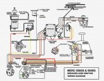
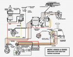
1968mercurydiagram.jpg 1968mercurydiagram.jpg
Time to verify wiring. I attempted to ohm out the original harness to determine if my CDI replacement harness had all of the wires in the correct position. As far as I can tell it does. Looking at the attached diagram, since it is the most accurate appearing one for my motor, it appears the red wire to the recitifier and the red wire to the switch box are hot all of the time. It also seems the red jumper attached to the switch box shares a lug on the box. Is this correct. My CDI harness and my original harness differ in this area. On the original there were three red wires that I believe all originate from the main battery wire. One goes to the solenoid, one to the recitifier, and the other to the switch box. On the diagram it shows two, one to the solenoid and one to the switch box. Then there is a jumper from the switch box to the recitifier to pick up 12 volt power. Now, my CDI harness has an extra small black wire that seems to ohm out to come from the ground. Is it an additional ground for the solenoid?
 

GA_Boater

Honorary Moderator Emeritus
Joined
May 24, 2011
Messages
49,038
If the CDI harness is a 414-2770, the black wires are explained below from the CDI Instructions. The small black goes to the ground connection on the solenoid like the diagram above.

batign.PNG

altign.PNG
 

jboehm

Cadet
Joined
Nov 27, 2011
Messages
29
Okay, black wire confirmed. The instructions say to connect the small red wire directly to the rectifier. it doesn't say anything about adding a jumper from the rectifier to the switch box, but I can see the connection in this diagram and my original had a hot connection to the switch box,
 

jboehm

Cadet
Joined
Nov 27, 2011
Messages
29
Speaking of the CDI instructions. What is the difference between Battery type ignition and alternator driven ignition? Which one do I have? The instructions for Battery type seem to best match up with my original harness, but not exactly.
 

GA_Boater

Honorary Moderator Emeritus
Joined
May 24, 2011
Messages
49,038
All I know for sure is to see what part number the switch box is.

I think an alternator system can be started with a dead battery and a battery driven one needs a charged battery. Something like that.
 

merc850

Commander
Joined
Jul 7, 2010
Messages
2,050
The ADI system uses power generated from the stator to fire the multiple coils - the CDI system like yours uses battery power to fire the (1) coil; from 5 to 19 volts.
 

jboehm

Cadet
Joined
Nov 27, 2011
Messages
29
The ADI system uses power generated from the stator to fire the multiple coils - the CDI system like yours uses battery power to fire the (1) coil; from 5 to 19 volts.
Am I correct that the rectifier and switch box will always have battery power if the battery is hooked up? The CDI instructions say to run the small red wire first to the rectifier then jumper it over to the switch box. I wired mine like the diagram, first to the switch box then jumper it to the rectifier. If the small red wire is always hot then it shouldn't matter.
 

jboehm

Cadet
Joined
Nov 27, 2011
Messages
29
After messing with this for almost a year I finally found time to start it. IT RAN!... for a minute. After getting it to start and run on the muffs I set it up to run in my test barrel. When I went to pump the bulb it wouldn't get hard and I found gas running out of the top carb. I did try to start it , but it wouldn't fire. Should it have at least run some with the carb leaking? I am trying to determine if there is now another problem besides the carb. As for the carb, Does it sound like a stuck float?
 
Top