Roughing In Front Motor Mounts Location Question

76SeaRay

Lieutenant Junior Grade
Joined
Aug 24, 2017
Messages
1,071
Now that my new transom is in and I am starting on the stringers, I need to know for sure where my front motor mounts will land before putting in the new stringers and floor. This boat originally had an OMC Windsor 351 in it with an OMC stringer drive so want to be sure the 5.7L Alpha One is going to fit correctly or make adjustments as I rebuild the stringers in that area. So, here is what I am thinking I will do to rough in the motor mount locations (looking for feedback on the idea).

My outdrive is completely disassembled for repainting and rebuild, however, the old gimbal bearing is still in the gimbal housing. I plan to temporarily mount the inner transom plate and the gimbal housing (without reassembling it) to the transom. Then, lift the engine into place on the inner transom plate rear mounts and with the motor mounts attached to the engine. Using the alignment procedure and the old gimbal bearing, align the engine close to what it should be. I will have the front mounts adjusted to the center of their vertical travel for height. In theory, I would then have the proper stringer/floor mount location based upon the bottom of the engine mounts. That would allow me to rebuild the stringers in the engine "box" location (stringers closest to the center of the boat do not run continuous to the front of the boat but rather form a box). Once the engine "box" is rebuilt and I know the engine fits with the appropriate clearance, I would then have reference points for the rest of the stringers.

So, does this approach have any pitfalls for getting the engine mount locations correct using a rough engine alignment as I described with a mostly disassembled gimbal housing?

Thanks....
 

Rick Stephens

Admiral
Joined
Aug 13, 2013
Messages
6,118
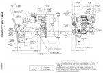
Based on the drawings that Chris gave you in post #3, and after mounting the inner transom plate, you can make a jig to set motor mount pad height.

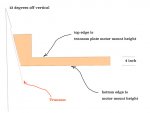
The drawing shows that the centerline of the motor is 13º down from the plane of the transom. Doesn't matter what angle the transom itself is, the engine centerline is 13º down from it. You can set the front motor mount pads exactly 4" below the top of the transom plate motor mounts after making a jig like this:

Click image for larger version  Name:	jig.jpg Views:	2 Size:	27.7 KB ID:	10871563

I used a piece of angle iron set across the top of the transom plate motor mounts and held the jig up against the angle iron so top edge is against the angle and bottom edge is top of front mount pads.

Click image for larger version  Name:	trimmed off.jpg Views:	1 Size:	235.3 KB ID:	10871564 You can see the jig on the left lower corner. It was held up under the angle with the 13 degree vertical edge held against the transom itself.

RIck
 

76SeaRay

Lieutenant Junior Grade
Joined
Aug 24, 2017
Messages
1,071
Hey that's great... Thanks for the info.. My transom is 10 to 11 degrees so that means the nose of the engine just sits a little lower vertically than the rear of the engine.. The drawing shows 3 1/2 inches from the crank center line to the base of the motor mount (mount adjusted to mid travel) so I assume the top of the rear motor mount (on the inner transom plate falls about 1/2 inch above the center line to get to the 4 inches you show for the fixture...
 

alldodge

Moderator
Staff member
Joined
Mar 8, 2009
Messages
42,873
Same thinking but, that line isn't the crank center line, its the rear motor mount reference plane. The front mounts are 3 1/2 below the transom assembly mounts
 

76SeaRay

Lieutenant Junior Grade
Joined
Aug 24, 2017
Messages
1,071
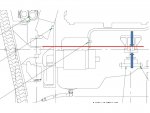
Ok, so a bit confused here... Right in front of the seawater pump and damper, it has 3 1/2 inches from the crankshaft center line (annotated just to the right) down to the bottom of the front motor mount... If I follow what is shown as the crankshaft center line back to the inner transom plate, it appears that centerline passes just below (by a very little bit) the top of the motor mount on the inner transom plate... I will see if I can mark up the image later tonight to point out what I am seeing... I don't have a tool to blow up the image and mark it on this computer...
 

Rick Stephens

Admiral
Joined
Aug 13, 2013
Messages
6,118
Same thinking but, that line isn't the crank center line, its the rear motor mount reference plane. The front mounts are 3 1/2 below the transom assembly mounts

Nope, the motor mount pads are 3.5 inches below CRANKSHAFT Centerline. The rear mounts are 1/4" above that. Better to be a 1/4" too low since you can adjust upwards over an inch, than to be too tall.

MCM5L.jpg
 

Rick Stephens

Admiral
Joined
Aug 13, 2013
Messages
6,118
Hey that's great... Thanks for the info.. My transom is 10 to 11 degrees so that means the nose of the engine just sits a little lower vertically than the rear of the engine.. The drawing shows 3 1/2 inches from the crank center line to the base of the motor mount (mount adjusted to mid travel) so I assume the top of the rear motor mount (on the inner transom plate falls about 1/2 inch above the center line to get to the 4 inches you show for the fixture...

You are correct. The nose of the motor will be a couple degree lower than the rear. Also correct that the 3 1/2" below Crank CL is the key. The rear motor mounts are a bit over 1/4" above that. When the leather pads are on them they come closer to 4". I would much prefer the mount pads to be a little low than a little high. You could always stick a 1/4" aluminum shim under them. Won't need to if you stay at 4" under.
 

alldodge

Moderator
Staff member
Joined
Mar 8, 2009
Messages
42,873
bit over 1/4" above that

So we don't know the difference between this dimension but guess its not that big a deal because the length of the mount stud. Its a SWAG

diff.jpg
 

Rick Stephens

Admiral
Joined
Aug 13, 2013
Messages
6,118
Before I built mine, I actually looked at a neighbors V8 Mercruiser and got a best eyeball with a tape measurement with the driveshaft installed where I could see it.. The 4" number is golden, hit the exact right place on my motor mounts when I installed the engine. V6 and V8 of course are same vertical dimensions. I am confident it works even though Mercruiser doesn't spec that. The actual height of the rear mounts to the centerline is less than 4". Which is perfect to make alignment within mount bolt adjustment heights. As stated, rather be teensy bit low that too high.
 

76SeaRay

Lieutenant Junior Grade
Joined
Aug 24, 2017
Messages
1,071
Great, sounds like we were at the same point just saying it differently.. I agree that the 4 inches sounds right on... I am going to pick up a piece of angle iron tonight.. I think I will bolt it onto the inner transom plate and use that as my aft reference line for measurements while I rebuild the engine "box"..
 

76SeaRay

Lieutenant Junior Grade
Joined
Aug 24, 2017
Messages
1,071
True but finding a straight 2x4 these days seems to be a challenge.... I was actually looking at aluminum angle last night. I like its clean edges from measurements and holding the end of a tape measure. Light weight and smaller than moving 2x4's around. Thinking I will use the angle bolted to the inner transom plate and then add an angle all the way across the floor in front of the engine bay at the back of the fuel tank to give me measurement points to replace the engine "box" stringers and plates... Putting another at the front of the belly gas tank approximately amidships would give me good accurate points with clean measurement edges to replace all the stringers and flooring... Anyway, next step is just the engine bay mounting... Hope to have the engine ready to fire on an engine stand in a few weeks...
 
Top