Re: slickcraft reseal,, well repower..... well reglass etc. etc.
After much deliberation and searching as many threads as I could, I decided how to build my engine mount stringers. The originals were 2) 1x oak laminated together with a single 3/4 plywood top. This created a box and the top 3/4 ply ran outboard to the main stringer. (very similar to what oops described his original mounts as). Mind you, this was a stringer mounted omc drive and the entire drive system was lag bolted through the SINGLE layer of ply! Not one of the mount lags went into the oak. The inside of the mount "boxes" were totally rotted.
I searched all last week on engine mount stringers trying to find a better mousetrap and this is what I decided to do.
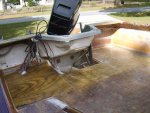
My new mounts are based on the similar design of the boxed in stringer, but I sandwiched 1 3/4" LVL beam material between 3/4" a/c plywood. In effect creating a laminated stringer. I am still topping it off with a layer of 3/4" a/c, but I have vented it fore and aft instead of sealing it.
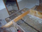
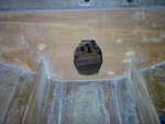
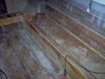
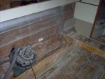
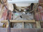
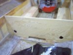
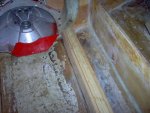
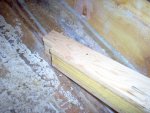
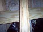
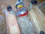
Today was just cutting the components. I am going to saturate them with CPES and wrap them individually with 4 oz cloth before installing them. I was thinking about installing them individually in the boat. First installing the inner 3/4 ply and bedding it in. then glueing and clamping the LVL and bedding it in, Then the last 3/4 ply layer and doing the same. Being that they are 3 1/4" wide stringers I figured this would create a better bond without any air pockets. then I will tab the completed stringer to the hull with 24 oz. roving and wrap them with another layer of 24 oz. Once that is set then I will install the 3/4 cap and lay 2 more layers of 24 oz. over the entire mount. I was really concerned about getting moiture inside the cavity, but the underside of the original cap didn't even have a layer of resin, and the cavity wasn't vented. The pictures below show holes in the bulkhead right below the bottom side of the cap to allow venting. In between the holes and below I notched the bulkhead for bilge drainage. In the picture of the side of the stringer, you can see I notched the bottom of the rear to allow for drainage from the engine mount cavity to the bilge. The reason for laminating the LVL between 2 layers of ply is so that the engine mount lags will run down into the direct center of the LVL, not running through the cap into the cavity as was the original design. once I drill the lag holes I will fill with CPES. once cured I will use 3m 4200 in the lag bolt holes before I run them in.
Took quite a bit longer than I thought, but even after a week of thinking on it, it was still "design as you go" (but I was armed with a lot of info from you all), man I hate doing searches here! Too Much INFO!!!!