Starter Coil wiring question

BlueNote2

Petty Officer 3rd Class
Joined
Nov 30, 2014
Messages
80
No Title

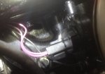
Found the purple wire from coil to choke @ the choke. Noticed that there are two purple wires.
Any suggestions here?
 

Attachments

  • photo213038.jpg
    photo213038.jpg
    188.1 KB · Views: 0
Last edited:

Fishermark

Vice Admiral
Joined
Oct 19, 2003
Messages
5,617
One of the wires will be the hot wire coming in, the other wire will be the resistance wire leading to the distributor. Not sure how to suggest telling them apart aside from cutting them off and seeing which one is hot - then bypass the other and add a new wire and crimp a new terminal end on.
 

wrestling coach

Petty Officer 1st Class
Joined
Jun 27, 2011
Messages
210
The resistance wire is a solid wire not stranded. Mine was silver/grey when I stripped away a small amount of insulation. It almost looked like a thin piece of solder only much stiffer. On the stranded purple wire at the choke+ I stripped back the insulation and soldered in my new wire going to coil+. Used liquid tape to cover the solder joint. At the coil I simply taped off my former resistance wire and secured it out of the way. I would suggest using solder for any new connections and not butt connectors.

Dennis
 
Last edited:

stonyloam

Vice Admiral
Joined
Mar 13, 2009
Messages
5,827
+1 with the coach, did mine the same way. Love my liquid tape! Look at the diagram. The purple/red wire on the slave should be "hot" all the time. You can make your alternator connection there. The R/Y wire will have battery voltage when the key is in the start position, and the P/Y wire will have battery voltage when the key is in either start or run position (with the new wire in place).
 
Last edited:

BlueNote2

Petty Officer 3rd Class
Joined
Nov 30, 2014
Messages
80
another question... Just to be sure.

After removing resistance wire...
am I splicing the the new wire onto the existing stranded wire that runs into the choke (no need to cut and re-join them-just strip insulation and solder together?)?
 

wrestling coach

Petty Officer 1st Class
Joined
Jun 27, 2011
Messages
210
Yes. Splice to the stranded purple wire at choke+. Just give yourself enough stripped wire off your stranded purple wire and wrap YOUR new wire into it and solder it up. Seal the new connection with liquid tape to keep moisture out and corrosion from forming. No need to remove the former solid resistance wire. Just tape it off at the coil end and secure it out of the way.

Dennis
 
Last edited:

BlueNote2

Petty Officer 3rd Class
Joined
Nov 30, 2014
Messages
80
dumb question:
do I put the rotor back on after installing the electronic ignition?
 

stonyloam

Vice Admiral
Joined
Mar 13, 2009
Messages
5,827
You seem kind of new at this, so here is the deal: The points are simply a switch that allows current to flow through the primary windings of the coil. The dwell is the the number of degrees of rotation of the distributor shaft where the points are closed and the current flows, the amount of TIME the points are closed varies with engine RPM. Your Petronix does the same thing except it can electronically change the dwell in relation to the engine RPM to make the coil work more efficiently. Works like this: points close, current (12v) flows through coil primary windings (few) to ground, building up a magnetic field. The points open, current stops and the field collapses. The collapsing magnetic field generates a high voltage (20,000+) in the coil secondary windings (many). The HV flows through the coil high voltage wire to the center of the distributor down through the carbon button into the rotor contact, where if your timing is correct it jumps over to the pluge wire contact, travels through the plug wire to the plug where it jumps the gap to ground and the plug fires. So as Dennis said, yes LOL.
 
Last edited:

BlueNote2

Petty Officer 3rd Class
Joined
Nov 30, 2014
Messages
80
No Title

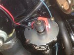
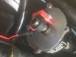
I completed splicing the wires together (soldering and liquid taping as advised). Everything else is finished also, except that I am a little hung up on the Electronic ignition.
Does this look right?
There is also a blue magnet that came with package, looks like the black one.

The rotor does not seem to want to seat like it did before, but spins freely, does not sit into notch.
 

Attachments

  • photo213093.JPG
    photo213093.JPG
    152.4 KB · Views: 0
  • photo213094.JPG
    photo213094.JPG
    187.1 KB · Views: 0
Last edited:

stonyloam

Vice Admiral
Joined
Mar 13, 2009
Messages
5,827
The magnet on the shaft should slide down farther over the distributor cam lobes. Pull the magnet off, put the rotor on and make a mark on the shaft at the bottom of the rotor. Pull the rotor back off and slide the magnet down to the mark. It may be a tight fit.
 
Last edited:

wrestling coach

Petty Officer 1st Class
Joined
Jun 27, 2011
Messages
210
Stony has it. The magnetic pickup is not seated yet. Are you placing a socket over the shaft and TAPPING the magnetic pickup home? There is no way the rotor should spin. It has a key inside that engages the slot you can see in your distributor shaft. You are NOT there yet keep TAPPING it down. If you pay attention the sound as you TAP will change the second you have bottomed it out. Your pictures are good and help a lot!

Dennis
 
Last edited:

BlueNote2

Petty Officer 3rd Class
Joined
Nov 30, 2014
Messages
80
No Title

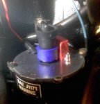
The Blue magnet fit better, with less force, so I just used that one.

Does the wiring look right coming out of this?


Don't know how I can thank you guys, you saved me a lot of frustration (not to mention the money I would have had to pay someone else to do it!)
(I have had the boat parked in my garage for about 3 months now - wife loves it there, not! Waxed it and put new pin-striping on, and making a fishing platform. Plan on doing some minor fiberglass repair in near future. This has been a great forum getting this far. i.e.., 470 alternator conversion, electronic ignition conversion, etc...)
 

Attachments

  • photo213095.jpg
    photo213095.jpg
    32.9 KB · Views: 0
Last edited:

wrestling coach

Petty Officer 1st Class
Joined
Jun 27, 2011
Messages
210
Is this a Pertronix kit? Anyway we won't know how you did until you get a chance to start it. There are a few guys here that know these 470's from top to bottom. I'm trying to catch them but am not there yet. Come here for any of your questions. There is NEVER a dumb question. We are here to help. Keep this engine running cool at 160*. Never ever,ever,ever overheat it. Keep a fresh impellar and its housing in it. Change the impellar every second season. Your welcome we are glad to help you out.

Dennis
 

BlueNote2

Petty Officer 3rd Class
Joined
Nov 30, 2014
Messages
80
Yes, it is a Pertronix kit.

I don't know what an impeller is. Can you possibly point me to a good thread on how to change one? Is this very difficult?
 

wrestling coach

Petty Officer 1st Class
Joined
Jun 27, 2011
Messages
210
The impellar pulls the lake water up and into your heat exchanger. It is located in the lower leg of your outdrive near the propeller. It would be best left to a marine mechanic to check/replace yours at this point.The heat exchanger is the large round cylinder you see mounted on the side of your engine just above your starter. Think of it as the radiator in your car. Here the hot coolant from the closed system in your engine (anti freeze and water just like your car) runs through tubes inside the exchanger and removes engine heat before it returns that coolant to your engine. The impellar is critical to ensure the maximum amount of cool lake water is drawn through the heat exchanger to keep the engine coolant (anti freeze/water) as cool as possible to keep the engine temp down. This engine is unique because it has an IRON cylinder head but an ALUMINUM block. Two metals that expand and contract at different rates especially when overheated. The dilemma is that when these engines get overheated the head gaskets get compromised because of the two metals. This causes coolant leaks and serious problems from there. Just keep your eye on your temp gauge ALWAYS.

Dennis
 

BlueNote2

Petty Officer 3rd Class
Joined
Nov 30, 2014
Messages
80
No Title

Thank you, Dennis. I have been reading a lot about the 470's, and am starting to see what is needed to keep this engine running well. I bought this used, and have no service records beyond 2011. Probably should have mechanics do it in Spring before using.

I had a question about the alternator before I consider it done:

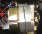
There is a bolt on top of the alternator that is unused. Should I have a wire going to it for any reason??? Not sure what it is there for. There were only two wires from Alternator (on going to Solenoid, and one going to + side of coil). Directions were confusing but I don't think there was any mention about this bolt.
 

Attachments

  • photo213112.JPG
    photo213112.JPG
    171.5 KB · Views: 0
  • photo213113.JPG
    photo213113.JPG
    181.9 KB · Views: 0
Last edited:

wrestling coach

Petty Officer 1st Class
Joined
Jun 27, 2011
Messages
210
That appears to me as a ground. In your application the alternator is grounded through the bracket. In other applications that bolt might be required. OK a caution here. I can't see your brackets BUT any bolts you removed from the water pump cover must have Permatex Aviation Sealer on them because they run into the coolant area of the water pump and could leak under pressure of the cooling system. A BIG HEADS UP. That cover is easily cracked if you tighten those bolts too tight. They should be torqued down with Permatex Aviation (NAPA) sealer. This is a NON HARDENING sealer that gets along with the aluminum block and iron head.

Dennis
 
Top