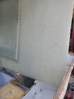
Stratos 1850 CC Rebuild Part 2

bakerjw

Petty Officer 1st Class
Joined
Apr 3, 2013
Messages
364
It was 12 or 13 years ago that I took my Stratos 1850 down to a bare hull and built it back up. Money was much tighter back then so I couldn't afford composite materials.
As fate would have it, water did get into the deck and transom so I resigned myself to another rebuild but this time using Coosa and Nidacore. I did identify how water got into the transom and that was alleviated. The transom is already finished with a few more layers of 1708 yet to be added.
The deck was installed in 3 sections with each section isolated from the others. That worked great.
The glass layer under the section of deck that got soft held as intended and the foam is dry as a bone as are the stringers and bulkheads. So far only a deck replacement.
The only one unseen issue was water intrusion where the fuel line and vent passed through the deck. The space between the hull and inside of the cap is very narrow and water that made it in to the bow area on the port side had nowhere to go. When I put the cap back on, I will see how much space is there and add a drain.
It sucks to do a project again but I am recently retired and now have the time to take it easy and make sure to never have to do it again.
 

bakerjw

Petty Officer 1st Class
Joined
Apr 3, 2013
Messages
364
Deck is off today! YAY!
There are 2 small bulkheads that might have gotten wet so I will replace them with Coosa and glass. We're talking not even square foot.
By the end of the week, the deck should be back in place.
 

bakerjw

Petty Officer 1st Class
Joined
Apr 3, 2013
Messages
364
Picture time. Been too busy to be posting.
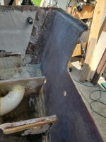
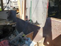
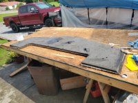
Stratos made their boats with a 2 part construction method. The hull was built out with a rough deck. and the cap was a bathtub that was then dropped in and glued to the deck of the hull and secured at the mating edges.
When I did the initial rebuild, I cut the cap from the original floor and then glued it to the new deck that I had built with a thickened epoxy mix. PITA to get cut back out. I had to use curved sawzall blades to get under the lip.

20260731_090330-s.jpg

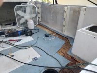
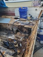
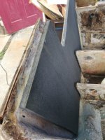
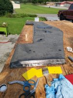
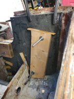
This is where I had water intrusion in the deck. Right by the 3 prong plug, you can see where the deck panels were partitioned.
20260731_090301-s.jpg

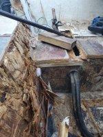
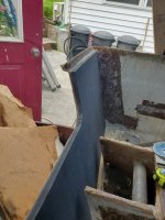
You can see the rot in the decking here.
20260731_143949-s.jpg

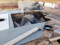
Even with some water intrusion, with the exception of near the fuel fill line, all of the foam was dry.
20260804_102733-s.jpg

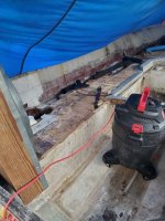
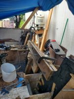
All of the deck off. A lot of VERY dry plywood. And messy.
20260821_120808-s.jpg

This shows where some water had gotten in my the fuel fill lines. The way everything was constructed, there was no gap between the hull and cap with the fuel line there so water pooled. I will be adding a drain line.
20260821_101802-s.jpg

Nothing that we've not seen before.
 

bakerjw

Petty Officer 1st Class
Joined
Apr 3, 2013
Messages
364
Transom Insanity!

Well, I had some air voids when I did the transom the last time and it came back to bite me as seen here. Lessons learned.

The typical, "Yeah, that's a wet transom." To quote Chong from Up in Smoke... "Hope you're not busy for about a month"
20260731_090359-s.jpg

With the cap off, it was much easier to get access to the wet wood. It was still solid but something that I cannot let go.
20260804_093613-s.jpg

The bilge looked pathetic but the stringers were all dry as a bone.
20260804_102135-s.jpg

Slowly making headway. I found a large crowbar with a sharpened edge worked well. Carpel tunnel to the max though.
20260804_102138-s.jpg

Down to glass with original tabbing that I had installed to be removed.
20260804_175636-s.jpg

Clean starboard side with tabbing removed.
Even with the wet transom, there were no signs of cracking or fatigue on any of my original work.
20260807_153128-s.jpg

Nice and clean fully sanded surface.
20260807_153152-s.jpg

From the other side.
All ready for a new transom.
20260809_104540-s.jpg
 

bakerjw

Petty Officer 1st Class
Joined
Apr 3, 2013
Messages
364
New transom time
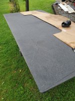
Using 2 sheets of 3/4" Coosa 30.

Template made and marked. Ready to cut.
20260809_104752-s.jpg

Checking fitment. As the original transom had been bedded with thickened epoxy and glass, it was not an exact fit so I had to adjust the bottom edge of the first piece. I left a very minimal amount of room between the Coosa and the hull.
20260809_110755-s.jpg

Starboard view
20260809_110759-s.jpg

With both pieces adjusted to fit the hull contour, I lightly clamped them in place.
20260809_135706-s.jpg

On the transom, there were 4 motor mount, 2 splash well drain, 2 hold down mount and 2 sculper holes.
20260810_110421-s.jpg

With the 2 panels in place and aligned nicely, I drilled out the holes for alignment purposes. I bevel cut the 2 sheets.
20260809_135716-s.jpg
 

bakerjw

Petty Officer 1st Class
Joined
Apr 3, 2013
Messages
364
Time to LAMINATE!!!

Using the alignment holes. I inserted 1/2" rubber tubing as I did the lamination. I used epoxy and 1708 glass between the 2 panels. 20260814_105349-s.jpg

It went very smoothly.
20260814_105403-s.jpg

20260814_105456-s.jpg

Once aligned, I used 1 5/8" drywall screws and started from the center and worked my way slowly to the edge. As I did so, epoxy started pushing up the guide holes.
20260814_105459-s.jpg

NOTE!!!!
I removed the screws after it was cured. ?I was lucky that I did so as when I installed the transom and started clamping it from the bottom up, air and epoxy started to ooze out. When it was just epoxy, I lightly put a screw back into the hole.
 

bakerjw

Petty Officer 1st Class
Joined
Apr 3, 2013
Messages
364
Installing the transom.

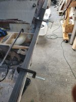
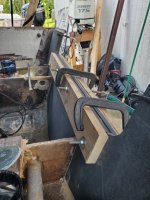
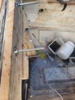
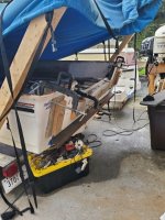
As I mentioned, When I originally reworked the transom, I had some thin air gaps between it and the outer skin of the hull. This time, I had multiple holes where I could use threaded rod and get much higher pressure between the new transom and the hull. Wooden shims were used between the stringers and the coosa as well. This all allowed me to stagger the pressure from the bottom to the top as I clamped things into place.

The first step was to lay a bed of very thick epoxy that was heavy with glass. The transom was set into it and bondo paddles were used to push it into and void as the base. This acted like a seal at the bottom.

Thickened epoxy was brushed onto the Coosa and a heavy coat brushed onto the hull surface prior to setting the transom in place. All of the threaded rod was lightly tightened up and I started with the rod through the drain hole seen at the bottom. After a minute, I drove in shims top the stringers.
20260815_153959-s.jpg

Through the sculper holes, I had a small I-Beam running across the outer skin to keep the surface flat.
The lower motor mount holes were used as part of the tee board that connected to the drain hole. These holes anchored on the outside to the I-Bean as well. The drain plug to lower motor holes was under heavy pressure. I noticed epoxy coming out screw holes so when it was just epoxy, I put screws back in place. The shims by the stringers were tapped again.
20260815_153933-s.jpg

The sculper threaded rods were tightened heavily. Pretty much the entire bottom of the transom and hull were under pressure and epoxy was pushing up toward the top.

The next 2 pictures show the rod from the I-Bean at the bottom and rod through the tie down holes applying pressure at the far edges of the transom.
Shims at work too.
20260815_153946-s.jpg


20260815_154004-s.jpg

So I now had a cup of sorts in the middle that was not under a lot of pressure. I opened the gap with some shims and added some regular mix epoxy which flowed down into the gap nicely. More epoxy was coming out of screw holes so they were filled. The splash well drain rods were tightened and finally the upper motor mount rods.
20260815_153940-s.jpg

Additional clamps were used at the edges where needed
If there are any voids now, I do not know what else I could have done.
 
Top